

Bravo & Brava • 1995 To 2000
Bravo & Brava • 1995 To 2000
Bravo & Brava • 1995 To 2000

Create successful ePaper yourself
Turn your PDF publications into a flip-book with our unique Google optimized e-Paper software.
11.5 Pedal pivot bolt (A) and clutch pedal<br />
return spring (B)<br />
3 Extract the split pin, and disconnect the<br />
clutch master cylinder pushrod from the<br />
clutch pedal.<br />
4 Remove the stop-light switch from the<br />
pedal bracket with reference to Section 17.<br />
5 Unscrew the pedal pivot bolt and withdraw<br />
it slowly to the right until it is possible to<br />
remove the clutch pedal from the bracket.<br />
Disconnect the clutch pedal return spring (see<br />
illustration).<br />
6 Extract the split pin, and disconnect the link<br />
from the arm on the brake pedal.<br />
7 Withdraw the pivot bolt and lower the brake<br />
pedal from the bracket.<br />
8 If necessary, remove the link and<br />
intermediate lever as follows. Extract the split<br />
pin, and disconnect the servo unit pushrod<br />
from the intermediate lever. Unscrew the pivot<br />
bolt and remove the assembly from the pedal<br />
bracket.<br />
9 Clean and examine the components for<br />
wear and damage (see illustration). Renew<br />
as necessary.<br />
Left-hand drive models<br />
10 Extract the split pin, and disconnect the<br />
brake servo unit pushrod from the pin on<br />
the brake pedal.<br />
11 Position the clutch pedal for access to the<br />
brake pedal pivot bolt. Unscrew the bolt and<br />
withdraw the pedal from the bracket.<br />
12 Recover the bushes, spacer and washers<br />
as necessary.<br />
13 Clean and examine the components for<br />
wear and damage. Renew as necessary.<br />
Refitting<br />
14 Refitting is a reversal of removal, but<br />
apply a little grease to the pedal bushes<br />
before reassembling them.<br />
12 Vacuum servo unit -<br />
testing, removal and refitting<br />
Testing<br />
1 <strong>To</strong> test the operation of the servo unit,<br />
depress the footbrake several times to<br />
exhaust the vacuum, then start the engine<br />
whilst keeping the pedal firmly depressed. As<br />
the engine starts, there should be a noticeable<br />
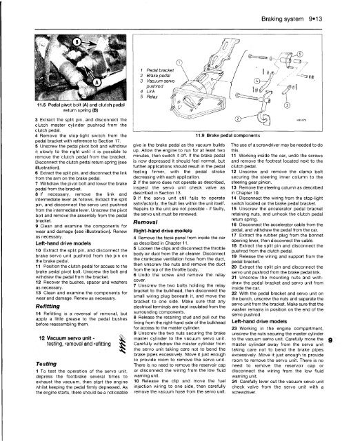
1 Pedal bracket<br />
2 Brake pedal<br />
3 Vacuum servo<br />
pushrod<br />
4 Link<br />
5 Relay<br />
give in the brake pedal as the vacuum builds<br />
up. Allow the engine to run for at least two<br />
minutes, then switch it off. If the brake pedal<br />
is now depressed it should feel normal, but<br />
further applications should result in the pedal<br />
feeling firmer, with the pedal stroke<br />
decreasing with each application.<br />
2 If the servo does not operate as described,<br />
inspect the servo unit check valve as<br />
described in Section 13.<br />
3 If the servo unit still fails to operate<br />
satisfactorily, the fault lies within the unit itself.<br />
Repairs to the unit are not possible - if faulty,<br />
the servo unit must be renewed.<br />
Removal<br />
Right-hand drive models<br />
4 Remove the facia panel from inside the car<br />
as described in Chapter 11.<br />
5 Loosen the clips and disconnect the throttle<br />
body air duct from the air cleaner. Disconnect<br />
the crankcase ventilation hose from the duct,<br />
then unscrew the nuts and remove the duct<br />
from the top of the throttle body.<br />
6 Undo the screw and remove the relay<br />
cover.<br />
7 Unscrew the two bolts holding the relay<br />
bracket to the bulkhead, then disconnect the<br />
small wiring plug beneath it, and move the<br />
bracket to one side. Make sure that any<br />
electrical terminals are kept insulated from the<br />
surrounding components.<br />
8 Release the retaining stud and pull out the<br />
lining from the right-hand side of the bulkhead<br />
for access to the master cylinder.<br />
9 Unscrew the two nuts securing the brake<br />
master cylinder to the vacuum servo unit.<br />
Carefully withdraw the master cylinder from<br />
the servo unit taking care not to bend the<br />
brake pipes excessively. Move it just enough<br />
to provide room to remove the servo unit.<br />
There is no need to remove the reservoir cap<br />
or disconnect the wiring from the low fluid<br />
warning unit.<br />
10 Release the clip and move the fuel<br />
injection wiring to one side, then carefully<br />
remove the vacuum hose from the servo unit.<br />
11.9 Brake pedal components<br />
Braking system 9*13<br />
The use of a screwdriver may be needed to do<br />
this.<br />
11 Working inside the car, undo the screws<br />
and remove the footrest located next to the<br />
clutch pedal.<br />
12 Unscrew and remove the clamp bolt<br />
securing the steering inner column to the<br />
steering gear pinion.<br />
13 Remove the steering column as described<br />
in Chapter 10.<br />
14 Disconnect the wiring from the stop-light<br />
switch located on the brake pedal bracket.<br />
15 Unscrew the accelerator pedal bracket<br />
retaining nuts, and unhook the clutch pedal<br />
return spring.<br />
16 Disconnect the accelerator cable from the<br />
pedal, and withdraw the pedal from the car.<br />
17 Extract the rubber plug from the bonnet<br />
opening lever, then disconnect the cable.<br />
18 Extract the split pin and disconnect the<br />
pushrod from the clutch pedal.<br />
19 Release the wiring and support from the<br />
pedal bracket.<br />
20 Extract the split pin and disconnect the<br />
servo unit pushrod from the brake pedal link.<br />
21 Unscrew the mounting nuts and withdraw<br />
the pedal bracket and servo unit from<br />
inside the car.<br />
22 With the pedal bracket and servo unit on<br />
the bench, unscrew the nuts and separate the<br />
servo unit from the bracket. Make sure that the<br />
washer remains in position on the end of the<br />
servo pushrod.<br />
Left-hand drive models<br />
23 Working in the engine compartment,<br />
unscrew the nuts securing the master cylinder<br />
to the vacuum servo unit. Carefully move the<br />
master cylinder away from the servo unit<br />
taking care not to bend the brake pipes<br />
excessively. Move it just enough to provide<br />
room to remove the servo unit. There is no<br />
need to remove the reservoir cap or<br />
disconnect the wiring from the low fluid<br />
warning unit.<br />
24 Carefully lever out the vacuum servo unit<br />
check valve from the servo unit with a<br />
screwdriver.


