

Bravo & Brava • 1995 To 2000
Bravo & Brava • 1995 To 2000
Bravo & Brava • 1995 To 2000

You also want an ePaper? Increase the reach of your titles
YUMPU automatically turns print PDFs into web optimized ePapers that Google loves.
4E>12 Fuel system - multi-point injection<br />
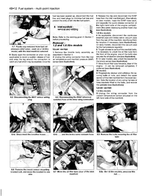
7.7 Plastic cap removed from fuel rail<br />
pressure relief valve - seen on a 1.6 litre<br />
model, with the inlet manifold removed<br />
9 Slowly open the connection or union nut (as<br />
applicable) to avoid a sudden release of fuel,<br />
and wrap the rag around the connection to<br />
catch any fuel which may be expelled. Once the<br />
8.2 Disconnecting the MAP sensor wiring<br />
plug<br />
8.4a Disconnect the breather hoses ...<br />
8.6 Remove the knock sensor mounting<br />
bracket bolt, and move the bracket to one<br />
side<br />
fuel has been soaked up, disconnect the fuel<br />
line, and insert plugs to minimise fuel loss and<br />
prevent the entry of dirt into the fuel system.<br />
8 Inlet manifold - §|<br />
removal and refitting ^<br />
Note: Refer to the warning given in Section 1<br />
before proceeding.<br />
Removal -<br />
1.2 and 1.6 litre models<br />
Upper section<br />
1 Remove the throttle body assembly as<br />
described in Section 4.<br />
2 Unplug the wiring connector from the inlet<br />
air temperature and manifold pressure (MAP)<br />
sensor (see illustration).<br />
8.3 Disconnecting the EVAP (charcoal<br />
canister) hose at the inner wing connection<br />
8.4b ... and the brake servo vacuum hose<br />
8.7 Move the oil filler tube clear of the inlet<br />
manifold<br />
3 Release the clip and disconnect the EVAP<br />
hose from the inlet manifold port. Alternatively<br />
on later models, trace the EVAP hose back,<br />
and separate the quick-release connection at<br />
the right-hand side of the engine compartment<br />
(this saves destroying another hose clip)<br />
(see illustration).<br />
1.6 litre models<br />
4 As applicable, disconnect the crankcase<br />
breather pipe and brake servo vacuum pipe<br />
from the rear of the manifold, identifying them<br />
for location if necessary (see illustrations).<br />
On early models, disconnect the vacuum pipe<br />
for the fuel pressure regulator.<br />
5 <strong>To</strong> gain access to some of the manifold bolts,<br />
it is necessary to unbolt the oil filler tube from<br />
the front of the engine; one of the bolts also<br />
secures the oil dipstick tube (see illustration).<br />
6 On later models, also unbolt the bracket for<br />
the knock sensor (see illustration).<br />
7 Move the oil filler tube forwards, clear of the<br />
engine - it can be removed completely if<br />
preferred (see illustration).<br />
All models<br />
8 Progressively slacken and withdraw the securing<br />
bolts or nuts, and detach the upper<br />
section of the inlet manifold from the lower section.<br />
Note the location of any wiring harness or<br />
hose brackets fitted to the bolts, and recover<br />
the gasket(s) (see illustrations).<br />
Lower section<br />
1.2 litre models<br />
9 Unplug the wiring connector from the<br />
coolant temperature sensor (situated on the<br />
left-hand side of the manifold).<br />
8.5 Remove the bolts securing the oil filler<br />
tube<br />
8.8a On 1.6 litre models, unscrew this<br />
nut...


