

Bravo & Brava • 1995 To 2000
Bravo & Brava • 1995 To 2000
Bravo & Brava • 1995 To 2000

You also want an ePaper? Increase the reach of your titles
YUMPU automatically turns print PDFs into web optimized ePapers that Google loves.
2A«4 1.2 litre engine in-car repair procedures<br />
2.6a <strong>To</strong> make an alternative camshaft<br />
locking tool...<br />
the help of a machine shop or engineering<br />
works, make up the camshaft locking tools by<br />
having the dowel rod or bolts machined to the<br />
dimensions shown (see illustrations). Note<br />
that two will be needed, one for each camshaft.<br />
Crankshaft setting tool<br />
fabrication<br />
7 <strong>To</strong> make the crankshaft setting tools, four<br />
old spark plugs will be required, together with<br />
four lengths of dowel rod. The length of each<br />
dowel rod is not critical, but it must be long<br />
enough to protrude about 100 mm above the<br />
top of the cylinder head extension when<br />
resting on top of a piston located half way<br />
down its bore. What is critical, however, is<br />
that all four dowel rods must be exactly the<br />
same length.<br />
8 Break off the ceramic upper section of each<br />
plug, and remove the centre electrode and<br />
earth tip. The easiest way to do this is to<br />
mount each spark plug in a vice (after<br />
removing the ceramic upper plug section) and<br />
drill a hole down through the centre of the<br />
plug. The diameter of the drill bit should be<br />
the same as the diameter of the dowel rod to<br />
be used. When finished, you should have four<br />
spark plug bodies and four equal-length<br />
dowel rods which will slide through the centre<br />
of the spark plugs.<br />
3 Cylinder compression test<br />
1 When engine performance is down, or if<br />
misfiring occurs which cannot be attributed to<br />
the ignition or fuel systems, a compression<br />
test can provide diagnostic clues as to the<br />
engine's condition. If the test is performed<br />
regularly, it can give warning of trouble before<br />
any other symptoms become apparent.<br />
2 The engine must be fully warmed-up to<br />
normal operating temperature, the battery must<br />
be fully charged, and all the spark plugs<br />
must be removed (Chapter 1). The aid of an<br />
assistant will also be required.<br />
3 Disable the ignition system by<br />
disconnecting the LT wiring plug to the<br />
ignition coil unit.<br />
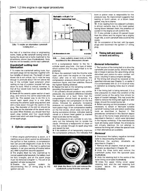
Suitable roll pin for<br />
25<br />
All dimensions In mm H 31234<br />
2.6b ... have suitable dowel rods or bolts<br />
machined to the dimensions shown<br />
4 Fit a compression tester to the No 1<br />
cylinder spark plug hole - the type of tester<br />
which screws into the plug thread is to be<br />
preferred.<br />
5 Have the assistant hold the throttle wide<br />
open, and crank the engine on the starter<br />
motor; after one or two revolutions, the<br />
compression pressure should build up to a<br />
maximum figure, and then stabilise. Record<br />
the highest reading obtained.<br />
6 Repeat the test on the remaining cylinders,<br />
recording the pressure in each.<br />
7 All cylinders should produce very similar<br />
pressures; any excessive difference indicates<br />
the existence of a fault. Note that the<br />
compression should build up quickly in a<br />
healthy engine; low compression on the first<br />
stroke, followed by gradually increasing<br />
pressure on successive strokes, indicates<br />
worn piston rings. A low compression reading<br />
on the first stroke, which does not build up<br />
during successive strokes, indicates leaking<br />
valves or a blown head gasket (a cracked<br />
head could also be the cause).<br />
8 If the pressure in any cylinder is very low,<br />
carry out the following test to isolate the<br />
cause. Introduce a teaspoonful of clean oil<br />
into that cylinder through its spark plug hole<br />
and repeat the test.<br />
9 If the addition of oil temporarily improves<br />
the compression pressure, this indicates that<br />
4.8 Undo the three bolts and remove the<br />
crankshaft pulley from the sprocket<br />
bore or piston wear is responsible for the<br />
pressure loss. No improvement suggests that<br />
leaking or burnt valves, or a blown head<br />
gasket, may be to blame.<br />
10 A low reading from two adjacent cylinders<br />
is almost certainly due to the head gasket<br />
having blown between them; the presence of<br />
coolant in the engine oil will confirm this.<br />
11 If one cylinder is about 20 percent lower<br />
than the others and the engine has a slightly<br />
rough idle, a worn camshaft lobe could be the<br />
cause.<br />
12 On completion of the test, refit the spark<br />
plugs and reconnect the ignition LT wiring<br />
plug.<br />
4 Timing belt and covers - g^><br />
removal and refitting<br />
General information<br />
1 The function of the timing belt is to drive the<br />
camshafts and coolant pump. Should the belt<br />
slip or break in service, the valve timing will be<br />
disturbed and piston-to-valve contact will<br />
occur, resulting in serious engine damage.<br />
2 The timing belt should be renewed at the<br />
specified intervals (see Chapter 1), or earlier if<br />
it is contaminated with oil, or if it is at all noisy<br />
in operation (a scraping noise due to uneven<br />
wear).<br />
3 If the timing belt is being removed, it is a<br />
wise precaution to check the condition of the<br />
coolant pump at the same time (check for<br />
signs of coolant leakage). This may avoid the<br />
need to remove the timing belt again at a later<br />
stage, should the coolant pump fail.<br />
4 Before carrying out this procedure, it will be<br />
necessary to obtain or fabricate suitable<br />
camshaft locking tools and piston positioning<br />
tools as described in Section 2. The<br />
procedures contained in this Section depict<br />
the use of the home-made alternative tools<br />
described in Section 2, which were fabricated<br />
in the Haynes workshop. If the manufacturers<br />
tools are being used instead, the procedures<br />
are virtually identical. Do not attempt to<br />
remove the timing belt unless the special tools<br />
or their alternatives are available.<br />
Removal<br />
5 Disconnect the battery negative terminal<br />
(refer to Disconnecting the battery).<br />
6 Remove the auxiliary drivebelts as<br />
described in Chapter 1.<br />
7 Remove the air cleaner, inlet air duct and<br />
resonator as described in Chapter 4B.<br />
8 Undo the three bolts and remove the<br />
crankshaft pulley from the sprocket (see<br />
illustration).<br />
9 Undo the retaining bolt in the centre of the<br />
lower timing cover (see illustration).<br />
10 Undo the upper timing cover upper<br />
retaining bolt, and the rear retaining bolt<br />
located above the alternator (see<br />
illustration).


