

Bravo & Brava • 1995 To 2000
Bravo & Brava • 1995 To 2000
Bravo & Brava • 1995 To 2000

You also want an ePaper? Increase the reach of your titles
YUMPU automatically turns print PDFs into web optimized ePapers that Google loves.
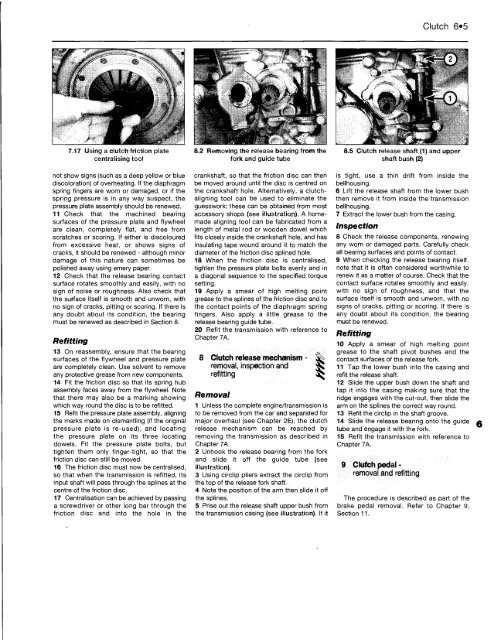
7.17 Using a clutch friction plate<br />
centralising tool<br />
not show signs (such as a deep yellow or blue<br />
discoloration) of overheating. If the diaphragm<br />
spring fingers are worn or damaged, or if the<br />
spring pressure is in any way suspect, the<br />
pressure plate assembly should be renewed.<br />
11 Check that the machined bearing<br />
surfaces of the pressure plate and flywheel<br />
are clean, completely flat, and free from<br />
scratches or scoring. If either is discoloured<br />
from excessive heat, or shows signs of<br />
cracks, it should be renewed - although minor<br />
damage of this nature can sometimes be<br />
polished away using emery paper.<br />
12 Check that the release bearing contact<br />
surface rotates smoothly and easily, with no<br />
sign of noise or roughness. Also check that<br />
the surface itself is smooth and unworn, with<br />
no sign of cracks, pitting or scoring. If there is<br />
any doubt about its condition, the bearing<br />
must be renewed as described in Section 8.<br />
Refitting<br />
13 On reassembly, ensure that the bearing<br />
surfaces of the flywheel and pressure plate<br />
are completely clean. Use solvent to remove<br />
any protective grease from new components.<br />
14 Fit the friction disc so that its spring hub<br />
assembly faces away from the flywheel. Note<br />
that there may also be a marking showing<br />
which way round the disc is to be refitted.<br />
15 Refit the pressure plate assembly, aligning<br />
the marks made on dismantling (if the original<br />
pressure plate is re-used), and locating<br />
the pressure plate on its three locating<br />
dowels. Fit the pressure plate bolts, but<br />
tighten them only finger-tight, so that the<br />
friction disc can still be moved.<br />
16 The friction disc must now be centralised,<br />
so that when the transmission is refitted, its<br />
input shaft will pass through the splines at the<br />
centre of the friction disc.<br />
17 Centralisation can be achieved by passing<br />
a screwdriver or other long bar through the<br />
friction disc and into the hole in the<br />
8.2 Removing the release bearing from the<br />
fork and guide tube<br />
crankshaft, so that the friction disc can then<br />
be moved around until the disc is centred on<br />
the crankshaft hole. Alternatively, a clutchaligning<br />
tool can be used to eliminate the<br />
guesswork; these can be obtained from most<br />
accessory shops (see illustration). A homemade<br />
aligning tool can be fabricated from a<br />
length of metal rod or wooden dowel which<br />
fits closely inside the crankshaft hole, and has<br />
insulating tape wound around it to match the<br />
diameter of the friction disc splined hole.<br />
18 When the friction disc is centralised,<br />
tighten the pressure plate bolts evenly and in<br />
a diagonal sequence to the specified torque<br />
setting.<br />
19 Apply a smear of high melting point<br />
grease to the splines of the friction disc and to<br />
the contact points of the diaphragm spring<br />
fingers. Also apply a little grease to the<br />
release bearing guide tube.<br />
20 Refit the transmission with reference to<br />
Chapter 7A.<br />
8 Clutch release mechanism -<br />
removal, inspection and<br />
refitting<br />
Removal<br />
1 Unless the complete engine/transmission is<br />
to be removed from the car and separated for<br />
major overhaul (see Chapter 2E), the clutch<br />
release mechanism can be reached by<br />
removing the transmission as described in<br />
Chapter 7A.<br />
2 Unhook the release bearing from the fork<br />
and slide it off the guide tube (see<br />
illustration).<br />
3 Using circlip pliers extract the circlip from<br />
the top of the release fork shaft.<br />
4 Note the position of the arm then slide it off<br />
the splines.<br />
5 Prise out the release shaft upper bush from<br />
the transmission casing (see illustration). If it<br />
Clutch 6*5<br />
8.5 Clutch release shaft (1) and upper<br />
shaft bush (2)<br />
is tight, use a thin drift from inside the<br />
bellhousing.<br />
6 Lift the release shaft from the lower bush<br />
then remove it from inside the transmission<br />
bellhousing.<br />
7 Extract the lower bush from the casing.<br />
Inspection<br />
8 Check the release components, renewing<br />
any worn or damaged parts. Carefully check<br />
all bearing surfaces and points of contact.<br />
9 When checking the release bearing itself,<br />
note that it is often considered worthwhile to<br />
renew it as a matter of course. Check that the<br />
contact surface rotates smoothly and easily,<br />
with no sign of roughness, and that the<br />
surface itself is smooth and unworn, with no<br />
signs of cracks, pitting or scoring. If there is<br />
any doubt about its condition, the bearing<br />
must be renewed.<br />
Refitting<br />
10 Apply a smear of high melting point<br />
grease to the shaft pivot bushes and the<br />
contact surfaces of the release fork.<br />
11 Tap the lower bush into the casing and<br />
refit the release shaft.<br />
12 Slide the upper bush down the shaft and<br />
tap it into the casing making sure that the<br />
ridge engages with the cut-out, then slide the<br />
arm on the splines the correct way round.<br />
13 Refit the circlip in the shaft groove.<br />
14 Slide the release bearing onto the guide<br />
tube and engage it with the fork.<br />
15 Refit the transmission with reference to<br />
Chapter 7A.<br />
9 Clutch pedal -<br />
removal and refitting<br />
The procedure is described as part of the<br />
brake pedal removal. Refer to Chapter 9,<br />
Section 11.


