

Bravo & Brava • 1995 To 2000
Bravo & Brava • 1995 To 2000
Bravo & Brava • 1995 To 2000

Create successful ePaper yourself
Turn your PDF publications into a flip-book with our unique Google optimized e-Paper software.
4A»10 Fuel system - single-point injection<br />
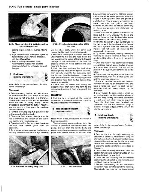
6.12a Make sure the ring nut is in position<br />
before fitting the unit<br />
sealing ring does not get pushed into the<br />
tank.<br />
d) Align the arrowhead marking on top of the<br />
tank with the similar mark on the sender<br />
unit (see illustration).<br />
e) Prior to refitting the access cover,<br />
reconnect the battery, then start the<br />
engine and check the unions for signs of<br />
leakage.<br />
7 Fuel tankremoval<br />
and refitting ^<br />
Note: Refer to the precautions in Section 1<br />
before proceeding.<br />
Removal<br />
1 Before removing the fuel tank, all fuel must<br />
be drained from the tank. Since a fuel tank<br />
drain plug is not provided, it is therefore<br />
preferable to carry out the removal operation<br />
when the tank is nearly empty. Before<br />
proceeding, disconnect the battery negative<br />
lead and syphon or hand-pump the remaining<br />
fuel from the tank.<br />
2 Remove the fuel pump/fuel gauge sender<br />
unit as described in Section 6.<br />
3 Chock the front wheels, then jack up the<br />
rear of the vehicle and support on axle stands<br />
(see Jacking and vehicle support).<br />
4 Open the fuel filler flap and carefully release<br />
the filler neck flexible gaiter from the<br />
bodywork.<br />
5 <strong>To</strong> improve access, remove the fasteners<br />
securing the rear wheel arch liner(s). Working<br />
7.7a Fuel tank retaining strap front...<br />
6.12b Arrowhead marking on top of the<br />
fuel tank<br />
via the wheel arch, undo the screw and<br />
release the filler neck from the bodywork.<br />
6 Position a trolley jack or similar centrally<br />
underneath the fuel tank and raise it until it is<br />
just supporting the weight of the tank. Prevent<br />
damage to the underside of the tank by<br />
placing a block of wood between the jack<br />
head and the tank.<br />
7 Undo the front and rear fuel tank strap<br />
securing bolts, recover the spacer washers,<br />
then carefully lower the fuel tank away from<br />
the floorpan (see illustrations). Loosen the<br />
clips and disconnect the EVAP purge hose<br />
and breather hose from the fuel tank as they<br />
become accessible.<br />
8 Check that all hoses and wiring 'are<br />
disconnected, then lower the tank to the<br />
ground and remove it from underneath the<br />
vehicle.<br />
Refitting<br />
9 Refitting is a reversal of the removal<br />
procedure, ensuring all hoses are correctly<br />
routed and securely reconnected.<br />
8 Fuel injection system - |^<br />
depressurisation ^<br />
Note: Refer to the precautions in Section 1<br />
before proceeding.<br />
1 The fuel supply system referred to in this<br />
Section is defined as the tank-mounted fuel<br />
pump, the fuel filter, the throttle body and<br />
pressure regulator components, and the metal<br />
pipes and flexible hoses of the fuel lines<br />
7.7b ... and rear bolts<br />
between these components. All these contain<br />
fuel which will be under pressure while the<br />
engine is running and/or while the ignition is<br />
switched on. The pressure will remain for<br />
some time after the ignition has been<br />
switched off, and must be relieved before any<br />
of these components are disturbed for<br />
servicing work.<br />
2 Make sure that the ignition is switched off<br />
(take out the key). Unscrew the knob and<br />
remove the cover from the fuse/relay holder<br />
directly behind the throttle body air box.<br />
3 Referring to Section 5, pull out the fuse for<br />
the fuel pump. If the injection/ignition fuse or<br />
the main system fuse are removed, the<br />
injector will not open, so defeating the<br />
purpose of this exercise.<br />
4 Try to start the engine, keeping the engine<br />
cranking for several seconds. It may fire and<br />
run for a little while - if so, let it run until it<br />
stops.<br />
5 Once the injector has opened and closed<br />
several times, this will reduce the fuel pressure<br />
to a safer level. However, fuel will still be<br />
present in the system, and care should still be<br />
taken.<br />
6 Disconnect the negative cable from the<br />
battery terminal, then refit the fuel pump fuse<br />
and the fuse/relay box cover.<br />
7 Place a container beneath the relevant<br />
connection/union to be disconnected, and<br />
have a large rag ready to soak up any<br />
escaping fuel not being caught by the<br />
container.<br />
8 Slowly loosen the connection or union nut<br />
(as applicable) to avoid a sudden release of<br />
fuel, and wrap the rag around the connection<br />
to catch any fuel which may be expelled.<br />
Once the fuel has been soaked up,<br />
disconnect the fuel line, and insert plugs to<br />
minimise fuel loss and prevent the entry of dirt<br />
into the fuel system.<br />
9 Inlet manifold - |^<br />
removal and refitting |S<br />
Note: Refer to the precautions in Section 1<br />
before proceeding.<br />
Removal<br />
1 Remove the throttle body assembly as<br />
described in Section 5. Alternatively, using the<br />
information in Section 5, disconnect the wiring<br />
plugs and hoses from the throttle body, and<br />
remove with the manifold as an assembly.<br />
2 Drain the cooling system as described in<br />
Chapter 1.<br />
3 Disconnect the wiring connector from the<br />
coolant temperature sensor (situated on the<br />
left-hand side of the manifold).<br />
4 Undo the bolt securing the accelerator<br />
cable mounting bracket to the manifold, and<br />
position it clear of the manifold.<br />
5 Slacken the retaining clip and disconnect<br />
the coolant hose from the rear of the manifold.<br />
Alternatively, this hose can be disconnected


