

Bravo & Brava • 1995 To 2000
Bravo & Brava • 1995 To 2000
Bravo & Brava • 1995 To 2000

You also want an ePaper? Increase the reach of your titles
YUMPU automatically turns print PDFs into web optimized ePapers that Google loves.
to the downpipe. The safest option (although<br />
involving more work) is to remove the exhaust<br />
manifold completely, as described.<br />
18 Working under the car, unscrew the four<br />
exhaust manifold-to-downpipe nuts, and<br />
separate the joint (see illustration). Recover<br />
the gasket.<br />
19 Unscrew the manifold-to-cylinder head<br />
nuts, and withdraw the manifold from the<br />
cylinder head, recovering the gasket.<br />
20 In some cases, the manifold studs will<br />
come out with the nuts - this poses no great<br />
problem, and the studs can be refitted if they<br />
are in good condition. For preference,<br />
however, a complete set of manifold and<br />
downpipe studs and nuts should be obtained<br />
as required, as the old ones are likely to be in<br />
less-than-perfect condition.<br />
21 If the downpipe is lowered to the floor,<br />
check that the wiring to the oxygen sensor (at<br />
the top of the downpipe) is not placed under<br />
strain. The wiring plug has already been<br />
disconnected, so feed the wiring through.<br />
22 Remove the bolt securing the upper end<br />
of the engine oil dipstick tube to the cylinder<br />
head, then pull the tube upwards to remove it<br />
(see illustration). Removing the tube may<br />
displace the seal at the base of the tube - if<br />
so, refit it now or store it with the tube for<br />
refitting.<br />
23 Check around the head that there are no<br />
further wires, hoses or other obstructions<br />
which will prevent the head from being lifted<br />
off.<br />
24 Unscrew the cylinder head Ribe bolts half<br />
a turn at a time, in the reverse order to that<br />
shown in illustration 9.42. When the bolts are<br />
free, remove them with their washers.<br />
25 Lift the cylinder head from the block,<br />
together with the inlet manifold. If it is stuck<br />
tight, insert pieces of wood into the exhaust<br />
ports (if possible), and use them as levers to<br />
rock the head off the block. On no account<br />
drive levers into the gasket joint, nor attempt<br />
to tap the head sideways, as it is located on<br />
positioning dowels.<br />
26 Remove and discard the cylinder head<br />
gasket and the manifold gaskets.<br />
27 The cylinder head can be dismantled after<br />
removing the camshaft and cam followers as<br />
described in Chapter 2E. Further dismantling<br />
and decarbonising are also described in<br />
Chapter 2E.<br />
Preparation for refitting<br />
28 The mating faces of the cylinder head and<br />
cylinder block must be perfectly clean before<br />
refitting the head. Use a hard plastic or<br />
wooden scraper to remove all traces of gasket<br />
and carbon; also clean the piston crowns.<br />
29 Take particular care when cleaning the<br />
piston crowns, as the soft aluminium alloy is<br />
easily damaged.<br />
30 Make sure that the carbon is not allowed<br />
to enter the oil and water passages - this is<br />
particularly important for the lubrication<br />
system, as carbon could block the oil supply<br />
9.18 Exhaust manifold-to-downpipe joint<br />
to the engine's components. Using adhesive<br />
tape and paper, seal the water, oil and bolt<br />
holes in the cylinder block.<br />
31 <strong>To</strong> prevent carbon entering the gap<br />
between the pistons and bores, smear a little<br />
grease in the gap. After cleaning each piston,<br />
use a small brush to remove all traces of<br />
grease and carbon from the gap, then wipe<br />
away the remainder with a clean rag. Clean all<br />
the pistons in the same way.<br />
32 Check the mating surfaces of the cylinder<br />
block and the cylinder head for nicks, deep<br />
scratches and other damage. If slight, they<br />
may be removed carefully with a file, but if<br />
excessive, machining may be the only<br />
alternative to renewal.<br />
33 If warpage of the cylinder head gasket<br />
surface is suspected, use a straight-edge to<br />
check it for distortion. Refer to Part E of this<br />
Chapter if necessary.<br />
34 Check the condition of the cylinder head<br />
bolts, and particularly their threads, whenever<br />
they are removed. Wash the bolts in a suitable<br />
solvent, and wipe them dry. Check each bolt<br />
for any sign of visible wear or damage,<br />
renewing them if necessary.<br />
Refitting<br />
35 Before refitting the assembled cylinder<br />
head, make sure that the head and block<br />
mating surfaces are perfectly clean.<br />
36 The bolt holes in the cylinder block must<br />
be mopped out to clear any oil or coolant. If<br />
the bolt holes have any significant amount of<br />
1.4 litre engine in-car repair procedures 2B«11<br />
9.22 Dipstick tube mounting bolt<br />
liquid in them, the block could be .cracked by<br />
hydraulic pressure when the head bolts are<br />
tightened.<br />
37 Check that the camshaft marks made<br />
during dismantling (see Section 4) are aligned.<br />
38 The new gasket should not be removed<br />
from its plastic bag until required for use. Fit<br />
the gasket dry - no grease or sealant should<br />
be used.<br />
39 Place the gasket on the cylinder block so<br />
that the word ALTO can be read from above.<br />
40 Lower the cylinder head onto the block so<br />
that it locates on the positioning dowels.<br />
41 Ensure that the cylinder head bolts are<br />
cleaned of all debris, and check the threads<br />
for signs of damage. Especially if it is known<br />
that the bolts have been removed previously,<br />
it is advisable to renew all ten bolts as a set,<br />
rather than risk the bolts shearing when<br />
tightened.<br />
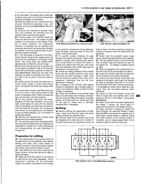
9.42 Cylinder head bolt tightening sequence<br />
42 Lightly oil the bolt threads. Screw the<br />
bolts in finger-tight, and tighten them in the 2B<br />
sequence shown to the Stage 1 torque (see<br />
illustration).<br />
43 When all ten bolts have been tightened to<br />
the Stage 1 torque, go round again in<br />
sequence and tighten to the Stage 2 torque.<br />
44 Again working in sequence, tighten the<br />
bolts through the specified Stage 3 angle.<br />
Note that 90° is equivalent to a quarter-turn or<br />
right-angle, making it easy to judge by noting<br />
the initial position of the socket handle. If<br />
available, use an angle gauge fitted to the<br />
socket handle for maximum accuracy.


