

Bravo & Brava • 1995 To 2000
Bravo & Brava • 1995 To 2000
Bravo & Brava • 1995 To 2000

Create successful ePaper yourself
Turn your PDF publications into a flip-book with our unique Google optimized e-Paper software.
4B»2 Fuel system - multi-point injection<br />
1 General information and<br />
precautions<br />
General information<br />
Three different types of engine<br />
management system are fitted to the multipoint<br />
fuel injection models covered in this<br />
Chapter. Each of the systems covered here is<br />
a self-contained engine management system,<br />
controlling both the fuel injection and ignition<br />
functions. This Chapter deals with the fuel<br />
injection system components only - refer to<br />
Chapter 5B for details of the ignition system<br />
components. Chapter 4A covers the fuel<br />
injection system components fitted to 1.4 litre<br />
models with single-point fuel injection.<br />
The engine management systems are very<br />
similar in their design and operation;<br />
similarities and differences are outlined in the<br />
following text.<br />
The fuel injection system comprises a fuel<br />
tank with an electric fuel pump, a fuel filter, fuel<br />
supply and return lines, a throttle body, a fuel<br />
rail with four electromagnetic fuel injectors,<br />
and an Electronic Control Unit (ECU) together<br />
with its associated sensors, actuators and<br />
wiring.<br />
The fuel pump has an integrated fuel gauge<br />
level sender and is mounted inside the fuel<br />
tank, immersed in the fuel. It delivers a<br />
constant supply of fuel through a cartridge<br />
filter to the throttle body and fuel pressure<br />
regulator (which is mounted on the fuel rail).<br />
The pressure regulator maintains a nearconstant<br />
fuel pressure at the fuel injectors,<br />
and returns excess fuel to the tank via the<br />
return line. This constant-flow system also<br />
helps to prevent localised fuel heating in the<br />
engine compartment, reducing the fuel<br />
vaporisation that can cause difficult hot<br />
starting. Note that all 1.2 litre, and later 1.6<br />
litre, models do not have a fuel return line or<br />
fuel rail-mounted pressure regulator; the<br />
pressure regulator is housed inside the fuel<br />
pump itself, in the fuel tank.<br />
The electromagnetic, pintle-type fuel<br />
injectors are opened and closed by an<br />
Electronic Control Unit (ECU), which<br />
calculates the injection timing and duration<br />
according to engine speed, throttle position<br />
and rate of opening, engine load, coolant<br />
temperature and exhaust gas oxygen content<br />
information, received from sensors mounted<br />
on and around the engine. The injectors are<br />
operated sequentially, so that the required<br />
quantity of fuel for each cylinder is injected<br />
once per cycle, on the induction stroke only.<br />
During starting, engine timing cannot be<br />
established until the crankshaft has started<br />
and rotated at least twice. During this time,<br />
banked injection is employed, ie fuel is<br />
injected into all cylinders simultaneously until<br />
the correct timing can be established.<br />
1.2 and 1.6 litre models measure engine<br />
load by calculating the mass of air entering<br />
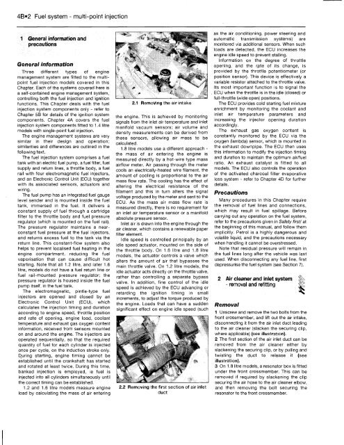
2.1 Removing the air intake<br />
the engine. This is achieved by monitoring<br />
signals from the inlet air temperature and inlet<br />
manifold vacuum sensors; air volume and<br />
density measurements can be derived from<br />
these sensors, allowing air mass to be<br />
calculated.<br />
1.8 litre models use a different approach -<br />
the mass of air entering the engine is<br />
measured directly by a hot-wire type mass<br />
airflow meter. Air passing through the meter<br />
cools an electrically-heated wire filament, the<br />
amount of cooling is proportional to the air<br />
mass flow rate. The cooling has the effect of<br />
altering the electrical resistance of the<br />
filament and this in turn alters the signal<br />
voltage produced by the meter and sent to the<br />
ECU. As the mass air mass flow rate is<br />
measured directly, there is no requirement for<br />
an inlet air temperature sensor or a manifold<br />
absolute pressure sensor.<br />
Inlet air is drawn into the engine through the<br />
air cleaner, which contains a renewable paper<br />
filter element.<br />
Idle speed is controlled principally by an<br />
idle speed actuator, mounted on the side of<br />
the throttle body. On 1.6 litre and 1.8 litre<br />
models, the actuator controls a valve which<br />
alters the amount of air that bypasses the<br />
main throttle valve. On 1.2 litre models, the<br />
idle actuator acts directly on the throttle valve,<br />
rather than controlling a separate bypass<br />
valve. In addition, fine control of the idle<br />
speed is achieved by the ECU advancing or<br />
retarding the ignition timing in small<br />
increments, to adjust the torque produced by<br />
the engine. Loads that can have a sudden<br />
significant effect on engine idle speed (such<br />
2.2 Removing the first section of air inlet<br />
duct<br />
as the air conditioning, power steering and<br />
automatic transmission systems) are<br />
monitored via additional sensors. When such<br />
loads are detected, the ECU increases the<br />
engine idle speed to prevent stalling.<br />
Information on the degree of throttle<br />
opening, and the rate of its change, is<br />
provided by the throttle potentiometer (or<br />
position sensor). This device is effectively a<br />
variable resistor attached to the throttle valve.<br />
Its most important function is to signal the<br />
ECU when the throttle is in the idle (closed) or<br />
full-throttle (wide open) positions.<br />
The ECU provides cold starting fuel mixture<br />
enrichment by monitoring the coolant and<br />
inlet air temperature parameters and<br />
increasing the injector opening duration<br />
accordingly.<br />
The exhaust gas oxygen content is<br />
constantly monitored by the ECU via the<br />
oxygen (lambda) sensor, which is mounted in<br />
the exhaust downpipe. The ECU then uses<br />
this information to modify the injection timing<br />
and duration to maintain the optimum air/fuel<br />
ratio. An exhaust catalyst is fitted to all<br />
models. The ECU also controls the operation<br />
of the activated charcoal filter evaporative<br />
loss system - refer to Chapter 4D for further<br />
details.<br />
Precautions<br />
Many procedures in this Chapter require<br />
the removal of fuel lines and connections,<br />
which may result in fuel spillage. Before<br />
carrying out any operation on the fuel system,<br />
refer to the precautions given in Safety first! at<br />
the beginning of this manual, and follow them<br />
implicitly. Petrol is a highly dangerous and<br />
volatile liquid, and the precautions necessary<br />
when handling it cannot be overstressed.<br />
Note that residual pressure will remain in<br />
the fuel lines long after the vehicle was last<br />
used. When disconnecting any fuel line, first<br />
depressurise the fuel system (see Section 7).<br />
2 Air cleaner and inlet system f^><br />
Removal<br />
- removal and refitting f|<br />
1 Unscrew and remove the two bolts from the<br />
front crossmember, and lift out the air intake,<br />
disconnecting it from the air inlet duct leading<br />
to the air cleaner (slacken the securing clip,<br />
where applicable) (see illustration).<br />
2 The first section of the air inlet duct can be<br />
removed from the air cleaner either by<br />
slackening the securing clip, or by pulling and<br />
twisting the duct to release it (see<br />
illustration).<br />
3 On 1.8 litre models, a resonator box is fitted<br />
under the front crossmember. This can be<br />
removed if required by slackening the clip<br />
securing the air hose to the air cleaner elbow,<br />
and then removing the bolt securing the<br />
resonator to the front crossmember.


