

Bravo & Brava • 1995 To 2000
Bravo & Brava • 1995 To 2000
Bravo & Brava • 1995 To 2000

Create successful ePaper yourself
Turn your PDF publications into a flip-book with our unique Google optimized e-Paper software.
1f>8 Suspension and steering systems<br />
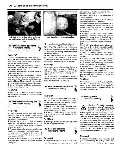
13.5 Rear brake hydraulic line and union<br />
nut on the underbody in front of the rear<br />
axle<br />
10 Rear suspension coil spring<br />
- removal and refitting Sfc<br />
Removal<br />
1 Chock the front wheels, then jack up the<br />
rear of the vehicle and support on axle stands<br />
(see Jacking and vehicle support). Remove<br />
the relevant rear roadwheel.<br />
2 Using a trolley jack positioned under the<br />
trailing arm, raise the trailing arm slightly to<br />
compress the coil spring.<br />
3 Unscrew and remove the shock absorber<br />
lower mounting bolt.<br />
4 Lower the trailing arm gradually on the trolley<br />
jack, until the coil spring is released from its<br />
lower seat on the trailing arm and its upper seat<br />
on the subframe. Make a note of the orientation<br />
of the coil spring, to ensure correct refitting later.<br />
5 Remove the upper and lower spring seats,<br />
and the bump stop rubbers.<br />
Refitting<br />
6 Refitting is a reversal of removal. Tighten<br />
the shock absorber lower mounting bolt to the<br />
specified torque.<br />
11 Rear suspension trailing arm %<br />
- removal and refitting ^<br />
Removal<br />
1 Chock the front wheels, then jack up the<br />
rear of the vehicle and support on axle stands<br />
(see Jacking and vehicle support). Remove<br />
the relevant rear roadwheel.<br />
2 Remove the brake drum and rear brake<br />
shoes as described in Chapter 9. Do not<br />
depress the brake pedal whilst the brake<br />
drum is removed.<br />
3 Fit a brake hose clamp to the flexible hose<br />
leading to the relevant rear brake. Unscrew<br />
the union nut from the rear of the rear wheel<br />
cylinder, then unbolt the brake line support<br />
from the trailing arm.<br />
4 Remove the handbrake cable from the<br />
backplate, then unbolt the backplate from the<br />
trailing arm.<br />
13.9 One of the rear axle mountings<br />
5 Remove the rear hub (Section 8) and coil<br />
spring (paragraphs 6 to 9 of this Section).<br />
6 Unbolt the anti-roll bar from the trailing arm.<br />
7 Unscrew and remove the front pivot bolt<br />
and withdraw the trailing arm from the rear<br />
suspension subframe.<br />
8 Check the bearings for excessive wear,<br />
particularly on the outer bearing. Note that it is<br />
not possible to renew the bearings separately;<br />
the complete trailing arm must be renewed.<br />
Refitting<br />
9 Refitting is a reversal of removal. Tighten all<br />
suspension fixings to the specified torque<br />
settings, but delay this operation until the full<br />
weight of the vehicle is resting on the<br />
roadwheels.<br />
10 On completion, bleed the brake hydraulic<br />
system and adjust the operation of the handbrake,<br />
with reference to Chapter 9.<br />
12 Rear suspension anti-roll bar %;<br />
- removal and refitting *k<br />
Removal<br />
1 Chock the front roadwheels, then jack up<br />
the rear of the vehicle and support on axle<br />
stands (see Jacking and vehicle support).<br />
Remove both rear roadwheels.<br />
2 Where fitted, disconnect the rear brake<br />
pressure proportioning valve spring from the<br />
middle of the rear anti-roll bar.<br />
3 Unscrew the bolts securing the anti-roll bar<br />
to the trailing arms, and withdraw it from<br />
under the car.<br />
Refitting<br />
4 Refitting is a reversal of removal, but tighten<br />
the mounting bolts securely.<br />
13 Rear axle assemblyremoval<br />
and refitting Sjk<br />
Removal<br />
1 Chock the front wheels, then jack up the<br />
rear of the vehicle and support on axle stands<br />
(see Jacking and vehicle support). Remove<br />
the relevant rear roadwheel.<br />
2 Remove the fuel tank as described in<br />
Chapter 4A or 4B.<br />
3 Remove the rear section of the exhaust<br />
system as described in Chapter 4C.<br />
4 Unscrew the filler cap from the brake fluid<br />
reservoir, and tighten it down onto a piece of<br />
polythene sheeting. This will reduce the loss<br />
of fluid when the brake lines are<br />
disconnected.<br />
5 Working under the rear of the car, identify<br />
for position then unscrew the union nuts and<br />
disconnect the rear brake hydraulic lines on<br />
the underbody in front of the rear axle (see<br />
illustration). Plug the lines to prevent loss of<br />
fluid.<br />
6 Back off the handbrake cable adjustment<br />
(see Chapter 9), and disconnect the cables<br />
from the equaliser bar. Also detach the outer<br />
cables from the underbody.<br />
7 Where necessary, unbolt and remove<br />
the ABS sensors from each rear brake<br />
backplate.<br />
8 Support the rear axle assembly with a<br />
trolley jack and length of wood. An assistant<br />
would also be helpful to steady the assembly<br />
as it is being lowered to the ground.<br />
9 Unscrew the four mounting bolts securing<br />
the rear axle assembly to the underbody, then<br />
lower it to the floor (see illustration).<br />
10 Remove the component parts of the rear<br />
axle assembly with reference to the relevant<br />
Sections of this Chapter.<br />
Refitting<br />
11 Refitting is a reversal of removal; tighten<br />
all nuts and bolts to the specified torque<br />
where given. Bleed the brake hydraulic<br />
system and adjust the handbrake cables as<br />
described in Chapter 9.<br />
14 Steering wheel - §^<br />
removal and refitting ^<br />
A<br />
Warning: For safety reasons,<br />
owners are strongly advised to<br />
entrust to an authorised FIAT<br />
dealer any work which involves<br />
disturbing the airbag system components.<br />
The airbag inflation devices contain<br />
explosive material and legislation exists to<br />
control their handling and storage. In<br />
addition, specialised test equipment is<br />
needed to check that the airbag system is<br />
fully operational following reassembly. The<br />
following information is given for the home<br />
mechanic who may have access to the<br />
necessary equipment and storage.<br />
Removal<br />
1 Disconnect the battery negative (earth) lead<br />
(see Disconnecting the battery). Note: The<br />
ignition must be switched off before


