

Bravo & Brava • 1995 To 2000
Bravo & Brava • 1995 To 2000
Bravo & Brava • 1995 To 2000

You also want an ePaper? Increase the reach of your titles
YUMPU automatically turns print PDFs into web optimized ePapers that Google loves.
hoist to the left-hand end of the inlet manifold,<br />
then take the weight of the engine. Make sure<br />
that the engine is well supported since only<br />
one other engine mounting will still be<br />
connected when the transmission is removed.<br />
Do not support the engine with a trolley jack<br />
positioned under the sump because the<br />
position of the right-hand front engine<br />
mounting dictates that the centre of gravity of<br />
the engine mass is high, and it is quite likely<br />
that the engine will fall to one side damaging<br />
either the radiator or the rear bulkhead. As an<br />
additional precaution, position axle stands<br />
and a block of wood beneath the engine.<br />
23 Unscrew and remove the upper and lower<br />
bolts securing the transmission to the engine,<br />
but leave the side nut and bolt at this stage.<br />
24 Support the transmission on a trolley jack.<br />
25 Working under the car, unbolt the rear<br />
engine mounting and bracket from the<br />
transmission and underbody.<br />
26 Unbolt the front engine mounting and<br />
bracket from the front valance and<br />
transmission.<br />
27 Lower the transmission and engine<br />
slightly until the transmission is clear of the<br />
left-hand inner body panels. Unscrew and<br />
remove the remaining rear mounting nut and<br />
front mounting bolt securing the transmission<br />
to the engine, then, with the help of an<br />
assistant, withdraw the transmission directly<br />
from the left-hand end of the engine. Do not<br />
allow the weight of the transmission to rest on<br />
the clutch friction disc hub.<br />
28 Lower the transmission to the ground and<br />
withdraw from under the car.<br />
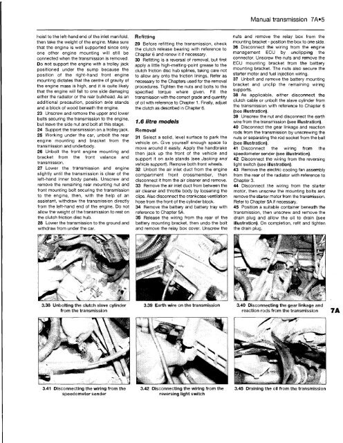
3.38 Unbolting the clutch slave cylinder<br />
from the transmission<br />
3.41 Disconnecting the wiring from the<br />
speedometer sender<br />
Refitting<br />
29 Before refitting the transmission, check<br />
the clutch release bearing with reference to<br />
Chapter 6 and renew it if necessary.<br />
30 Refitting is a reversal of removal, but first<br />
apply a little high-melting-point grease to the<br />
clutch friction disc hub splines, taking care not<br />
to allow any onto the friction linings. Refer as<br />
necessary to the Chapters used for the removal<br />
procedures. Tighten the nuts and bolts to the<br />
specified torque where given. Fill the<br />
transmission with the correct grade and quantity<br />
of oil with reference to Chapter 1. Finally, adjust<br />
the clutch as described in Chapter 6.<br />
1.6 litre models<br />
Removal<br />
31 Select a solid, level surface to park the<br />
vehicle on. Give yourself enough space to<br />
move around it easily. Apply the handbrake<br />
then jack up the front of the vehicle and<br />
support it on axle stands (see Jacking and<br />
vehicle support). Remove both front wheels.<br />
32 Unbolt the air inlet duct from the engine<br />
compartment front crossmember, then<br />
disconnect it from the air cleaner and remove.<br />
33 Remove the air inlet duct from between the<br />
air cleaner and throttle body by loosening the<br />
clips. Also disconnect the crankcase ventilation<br />
hose from the front of the cylinder block.<br />
34 Remove the battery and battery tray with<br />
reference to Chapter 5A.<br />
35 Release the wiring from the rear of the<br />
battery mounting bracket, then undo the bolt<br />
and remove the relay box cover. Unscrew the<br />
3.39 Earth wire on the transmission<br />
3.42 Disconnecting the wiring from the<br />
reversing light switch<br />
Manual transmission 7A»5<br />
nuts and remove the relay box from the<br />
mounting bracket - position the box to one side.<br />
36 Disconnect the wiring from the engine<br />
management ECU by unclipping the<br />
connector. Unscrew the nuts and remove the<br />
ECU mounting bracket from the battery<br />
mounting bracket. The nuts also secure the<br />
starter motor and fuel injection wiring.<br />
37 Unbolt and remove the battery mounting<br />
bracket and unclip the remaining wiring<br />
supports.<br />
38 As applicable, either disconnect the<br />
clutch cable or unbolt the slave cylinder from<br />
the transmission with reference to Chapter 6<br />
(see illustration).<br />
39 Unscrew the nut and disconnect the earth<br />
wire from the transmission (see illustration).<br />
40 Disconnect the gear linkage and reaction<br />
rods from the transmission by unscrewing the<br />
nuts or separating the rod socket from the ball<br />
(see illustration).<br />
41 Disconnect the wiring from the<br />
speedometer sender (see illustration).<br />
42 Disconnect the wiring from the reversing<br />
light switch (see illustration).<br />
43 Remove the electric cooling fan assembly<br />
from the rear of the radiator with reference to<br />
Chapter 3.<br />
44 Disconnect the wiring from the starter<br />
motor, then unscrew the mounting bolts and<br />
remove the starter motor from the transmission.<br />
Refer to Chapter 5A if necessary.<br />
45 Position a suitable container beneath the<br />
transmission, then unscrew and remove the<br />
drain plug and allow the oil to drain (see<br />
illustration). On completion, refit and tighten<br />
the drain plug.<br />
3.40 Disconnecting the gear linkage and<br />
reaction rods from the transmission<br />
3.45 Draining the oil from the transmission


