

Bravo & Brava • 1995 To 2000
Bravo & Brava • 1995 To 2000
Bravo & Brava • 1995 To 2000

Create successful ePaper yourself
Turn your PDF publications into a flip-book with our unique Google optimized e-Paper software.
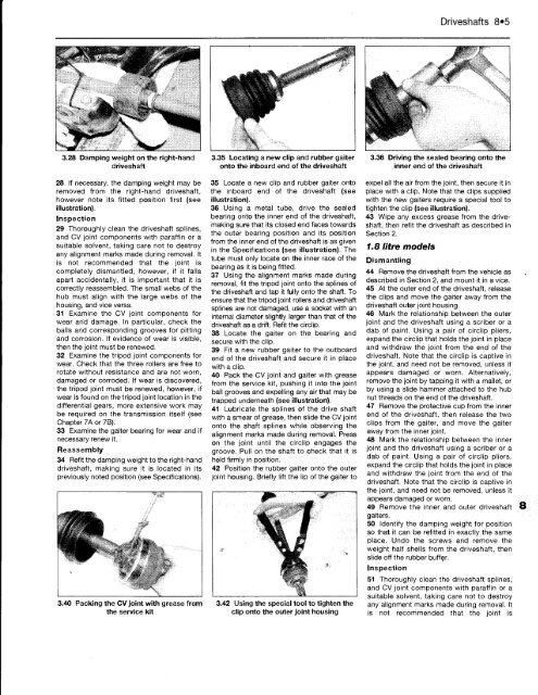
3.28 Damping weight on the right-hand<br />
driveshaft<br />
28 If necessary, the damping weight may be<br />
removed from the right-hand driveshaft,<br />
however note its fitted position first (see<br />
illustration).<br />
Inspection<br />
29 Thoroughly clean the driveshaft splines,<br />
and CV joint components with paraffin or a<br />
suitable solvent, taking care not to destroy<br />
any alignment marks made during removal. It<br />
is not recommended that the joint is<br />
completely dismantled, however, if it falls<br />
apart accidentally, it is important that it is<br />
correctly reassembled. The small webs of the<br />
hub must align with the large webs of the<br />
housing, and vice versa.<br />
31 Examine the CV joint components for<br />
wear and damage. In particular, check the<br />
balls and corresponding grooves for pitting<br />
and corrosion. If evidence of wear is visible,<br />
then the joint must be renewed.<br />
32 Examine the tripod joint components for<br />
wear. Check that the three rollers are free to<br />
rotate without resistance and are not worn,<br />
damaged or corroded. If wear is discovered,<br />
the tripod joint must be renewed, however, if<br />
wear is found on the tripod joint location in the<br />
differential gears, more extensive work may<br />
be required on the transmission itself (see<br />
Chapter 7A or 7B).<br />
33 Examine the gaiter bearing for wear and if<br />
necessary renew it.<br />
Reassembly<br />
34 Refit the damping weight to the right-hand<br />
driveshaft, making sure it is located in its<br />
previously noted position (see Specifications).<br />
3.40 Packing the CV joint with grease from<br />
the service kit<br />
\<br />
3.35 Locating a new clip and rubber gaiter<br />
onto the inboard end of the driveshaft<br />
35 Locate a new clip and rubber gaiter onto<br />
the inboard end of the driveshaft (see<br />
illustration).<br />
36 Using a metal tube, drive the sealed<br />
bearing onto the inner end of the driveshaft,<br />
making sure that its closed end faces towards<br />
the outer bearing position and its position<br />
from the inner end of the driveshaft is as given<br />
in the Specifications (see illustration). The<br />
tube must only locate on the inner race of the<br />
bearing as it is being fitted.<br />
37 Using the alignment marks made during<br />
removal, fit the tripod joint onto the splines of<br />
the driveshaft and tap it fully onto the shaft. <strong>To</strong><br />
ensure that the tripod joint rollers and driveshaft<br />
splines are not damaged, use a socket with an<br />
internal diameter slightly larger than that of the<br />
driveshaft as a drift. Refit the circlip.<br />
38 Locate the gaiter on the bearing and<br />
secure with the clip.<br />
39 Fit a new rubber gaiter to the outboard<br />
end of the driveshaft and secure it in place<br />
with a clip.<br />
40 Pack the CV joint and gaiter with grease<br />
from the service kit, pushing it into the joint<br />
ball grooves and expelling any air that may be<br />
trapped underneath (see illustration).<br />
41 Lubricate the splines of the drive shaft<br />
with a smear of grease, then slide the CV joint<br />
onto the shaft splines while observing the<br />
alignment marks made during removal. Press<br />
on the joint until the circlip engages the<br />
groove. Pull on the shaft to check that it is<br />
held firmly in position.<br />
42 Position the rubber gaiter onto the outer<br />
joint housing. Briefly lift the lip of the gaiter to<br />
3.42 Using the special tool to tighten the<br />
clip onto the outer joint housing<br />
Driveshafts 8*5<br />
3.36 Driving the sealed bearing onto the<br />
inner end of the driveshaft<br />
expel all the air from the joint, then secure it in<br />
place with a clip. Note that the clips supplied<br />
with the new gaiters require a special tool to<br />
tighten the clip (see illustration).<br />
43 Wipe any excess grease from the driveshaft,<br />
then refit the driveshaft as described in<br />
Section 2.<br />
1.8 litre models<br />
Dismantling<br />
44 Remove the driveshaft from the vehicle as<br />
described in Section 2, and mount it in a vice.<br />
45 At the outer end of the driveshaft, release<br />
the clips and move the gaiter away from the<br />
driveshaft outer joint housing.<br />
46 Mark the relationship between the outer<br />
joint and the driveshaft using a scriber or a<br />
dab of paint. Using a pair of circlip pliers,<br />
expand the circlip that holds the joint in place<br />
and withdraw the joint from the end of the<br />
driveshaft. Note that the circlip is captive in<br />
the joint, and need not be removed, unless it<br />
appears damaged or worn. Alternatively,<br />
remove the joint by tapping it with a mallet, or<br />
by using a slide hammer attached to the hub<br />
nut threads on the end of the driveshaft.<br />
47 Remove the protective cup from the inner<br />
end of the driveshaft, then release the two<br />
clips from the gaiter, and move the gaiter<br />
away from the inner joint.<br />
48 Mark the relationship between the inner<br />
joint and the driveshaft using a scriber or a<br />
dab of paint. Using a pair of circlip pliers,<br />
expand the circlip that holds the joint in place<br />
and withdraw the joint from the end of the<br />
driveshaft. Note that the circlip is captive in<br />
the joint, and need not be removed, unless it<br />
appears damaged or worn.<br />
49 Remove the inner and outer driveshaft<br />
gaiters.<br />
50 Identify the damping weight for position<br />
so that it can be refitted in exactly the same<br />
place. Undo the screws and remove the<br />
weight half shells from the driveshaft, then<br />
slide off the rubber buffer.<br />
Inspection<br />
51 Thoroughly clean the driveshaft splines,<br />
and CV joint components with paraffin or a<br />
suitable solvent, taking care not to destroy<br />
any alignment marks made during removal. It<br />
is not recommended that the joint is


