

Bravo & Brava • 1995 To 2000
Bravo & Brava • 1995 To 2000
Bravo & Brava • 1995 To 2000

You also want an ePaper? Increase the reach of your titles
YUMPU automatically turns print PDFs into web optimized ePapers that Google loves.
Refitting<br />
20 Refit the injectors and fuel rail by following<br />
the removal procedure, in reverse, noting the<br />
following points:<br />
a) Renew the O-ring seals before refitting<br />
the injectors. Take care when fitting the<br />
injectors to the fuel rail, and do not press<br />
them in further than required to fit the<br />
retaining clip, otherwise the O-ring seal<br />
may be damaged.<br />
b) Ensure that the injector retaining clips are<br />
securely seated.<br />
c) Make sure the fuel supply hose (and<br />
where applicable, the fuel return hose) are<br />
correctly fitted as noted on removal.<br />
d) Check that all vacuum and electrical<br />
connections are remade correctly and<br />
securely.<br />
e) On completion check the fuel rail and<br />
injectors for fuel leaks.<br />
Fuel pressure regulator<br />
Note: Later models with the 'returnless' fuel<br />
system (see Section 1) have their pressure<br />
regulator mounted inside the fuel pump/<br />
sender unit in the fuel tank. Refer to Section 5<br />
for details of pump/sender unit removal.<br />
Removal<br />
Early 1.6 litre models<br />
21 Remove the throttle body assembly as<br />
described earlier in this Section.<br />
22 Depressurise the fuel system as<br />
described in Section 7.<br />
23 Unplug the wiring connectors from the<br />
inlet air temperature and manifold pressure<br />
sensors.<br />
24 Release the clip and disconnect the EVAP<br />
hose from the inlet manifold port.<br />
25 Remove the upper section of the inlet<br />
manifold with reference to Section 8.<br />
26 Disconnect the vacuum hose from the<br />
port on the side of the regulator.<br />
27 Extract the retaining clip and pull the<br />
pressure regulator out of the fuel rail; recover<br />
the O-ring seal.<br />
1.8 litre models<br />
28 Remove the fuel rail and injectors as<br />
described earlier in this Section.<br />
29 Disconnect the vacuum hose from the<br />
port on the side of the regulator.<br />
30 Extract the retaining clip and pull the<br />
pressure regulator out of the fuel rail; recover<br />
the O-ring seal.<br />
Refitting<br />
31 Refit the fuel pressure regulator by<br />
following the removal procedure in reverse.<br />
Renew the O-ring seal and refit the vacuum<br />
hose securely.<br />
Idle air control valve<br />
(1.6 and 1.8 litre models)<br />
Removal<br />
32 Disconnect the battery negative cable,<br />
then unplug the wiring connector from the<br />
actuator valve (see illustration).<br />
33 On early models, undo the securing screws<br />
4.32 Disconnect the idle air control valve<br />
wiring plug<br />
and withdraw the valve from the throttle body<br />
(see illustration); on later models, unscrew the<br />
unit itself.<br />
Refitting<br />
34 Refit the actuator by following the removal<br />
procedure in reverse. Noting the following<br />
points:<br />
a) Clean the threads of the screws or valve<br />
body, and apply a coat of locking<br />
compound to the threads before refitting.<br />
b) Take great care to ensure that the plunger<br />
is correctly aligned with its bore, before<br />
tightening the actuator securing screws.<br />
c) Delay reconnecting the battery negative<br />
cable for about 20 minutes. After this, the<br />
ECU will correctly reposition the idle<br />
actuator valve when the engine is started<br />
for the first time.<br />
Idle actuator (1.2 litre models)<br />
Note: On 1.2 litre models, the throttle<br />
potentiometer is integral with the idle actuator.<br />
35 Disconnect the battery negative cable,<br />
then unplug the wiring connector from the<br />
actuator valve.<br />
36 Undo the securing screws and withdraw<br />
the valve from the throttle body.<br />
Refitting<br />
37 Refit the actuator by following the removal<br />
procedure in reverse.<br />
Throttle potentiometer<br />
Note: On 1.2 litre models, the throttle potentiometer<br />
is integral with the idle actuator.<br />
38 Disconnect the battery negative cable,<br />
then unplug the wiring connector from the<br />
potentiometer.<br />
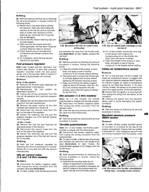
39 On early models, undo the securing screws<br />
and withdraw the valve from the throttle body<br />
(see illustration); on later models, the<br />
potentiometer appears to be integral with the<br />
throttle body.<br />
Refitting<br />
40 Refit the potentiometer by following the<br />
removal procedure in reverse, noting the<br />
following points:<br />
a) Note that the mounting holes are not<br />
slotted; no adjustment of the potentiometer's<br />
position is possible or necessary, as<br />
the ECU adapts to the potentiometer and<br />
'learns' the idle and full throttle positions.<br />
Fuel system - multi-point injection 4B»7<br />
4.33 Idle air control valve retaining screws<br />
(arrowed)<br />
b) On 1.8 litre models, ensure that drive dog<br />
on the sensor rotor is above the<br />
corresponding pin on the throttle disc<br />
shaft, when the sensor is refitted.<br />
c) Clean the threads of the screws or valve<br />
body, and apply a coat of locking<br />
compound to the threads before refitting.<br />
Intake air temperature sensor<br />
Removal<br />
41 On 1.2 litre and later 1.6 litre models, the<br />
intake air temperature sensor is integral with<br />
the manifold absolute pressure (MAP) sensor.<br />
On 1.8 litre models, an intake air temperature<br />
sensor is not fitted (see Section 1). On early<br />
1.6 litre models, the sensor is mounted at the<br />
rear of the upper section of the inlet manifold.<br />
42 Ensure that the ignition is switched off,<br />
then unplug the wiring from the sensor at the<br />
connector.<br />
43 Unscrew the sensor from the manifold,<br />
taking care to avoid damaging the plastic<br />
connector.<br />
Refitting<br />
44 Refit the sensor by following the removal<br />
procedure in reverse.<br />
Manifold absolute pressure<br />
(MAP) sensor<br />
Removal<br />
45 On early 1.6 litre models, the MAP sensor<br />
is mounted on a bracket at the rear of the<br />
engine compartment. Ensure that the ignition<br />
is switched off , then unplug the vacuum hose<br />
and wiring connector from the sensor, undo<br />
4.39 Disconnect the throttle potentiometer<br />
wiring plug - securing screws arrowed


