

Bravo & Brava • 1995 To 2000
Bravo & Brava • 1995 To 2000
Bravo & Brava • 1995 To 2000

Create successful ePaper yourself
Turn your PDF publications into a flip-book with our unique Google optimized e-Paper software.
9*8 Braking system<br />
5.27 Removing the self-adjuster<br />
mechanism from the trailing shoe<br />
1<br />
27 Remove the self-adjuster mechanism<br />
from the trailing shoe (see illustration).<br />
28 Using the pliers, release the trailing brake<br />
shoe steady spring from its pin, and remove<br />
the pin (see illustration).<br />
29 Turn over the trailing brake shoe and use<br />
a pair of pliers to disconnect the handbrake<br />
cable from the lever on the back of the shoe<br />
(see illustration).<br />
30 Thoroughly clean the surface of the<br />
backplate using brake component cleaner to<br />
remove all traces of dust and old lubricant.<br />
Examine all components for signs of<br />
corrosion.<br />
31 Apply brake grease sparingly to the shoe<br />
contact surfaces of the brake backplate (see<br />
illustration 5.10).<br />
32 Connect the handbrake cable to the lever<br />
on the back of the new trailing brake shoe.<br />
Use a pair of long-nosed pliers to hold the<br />
spring away from the end of the cable while it<br />
is being connected.<br />
33 Offer the trailing shoe up to the backplate<br />
and secure in position with the pin and steady<br />
spring.<br />
34 Before refitting the self-adjuster<br />
mechanism, fully screw in the adjustment<br />
screw so that the mechanism is set to its<br />
minimum length. Apply a little brake grease to<br />
the metal contact faces of both brake shoes,<br />
self-adjuster mechanism and handbrake lever<br />
(see illustration).<br />
35 Refit the self-adjuster mechanism to the<br />
trailing shoe, making sure it is the correct way<br />
round.<br />
36 Locate the leading shoe on the backplate<br />
5.34 The rear brake self-adjuster<br />
mechanism<br />
5.28 Removing the trailing brake shoe<br />
steady spring and pin<br />
and engage it with the self-adjuster<br />
mechanism. Refit the upper return spring.<br />
37 Locate the bottom of the trailing shoe on<br />
its anchor, then refit the bottom return spring<br />
and lever the leading shoe onto the anchor.<br />
38 Refit the steady spring and pin to the<br />
leading shoe. Remove the elastic band from<br />
the wheel cylinder.<br />
39 Repeat the procedure on the remaining<br />
side of the vehicle.<br />
40 Refit the brake drums as described in<br />
Section 7. Check and if necessary adjust the<br />
operation of the handbrake, as described in<br />
Section 14.<br />
41 Apply the brake pedal and handbrake<br />
lever several times to settle the self-adjusting<br />
mechanism. With both rear roadwheels<br />
refitted and the rear of the vehicle still raised,<br />
turn the wheels by hand to check that the<br />
brake shoes are not binding.<br />
42 Lower the vehicle to the ground and<br />
thoroughly check the operation of the braking<br />
system.<br />
A Warning:<br />
Front brake disc -<br />
inspection, removal<br />
and refitting<br />
Inspection<br />
Before starting work,<br />
refer to the warning at the<br />
beginning of Section 4 concerning<br />
the dangers of asbestos dust.<br />
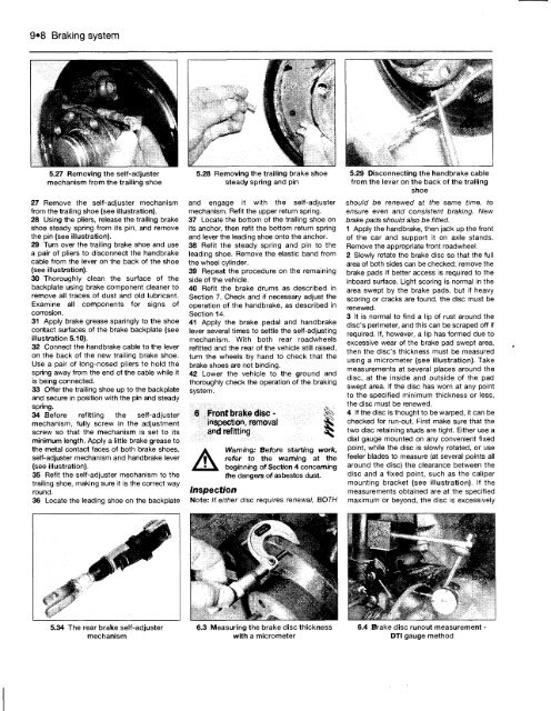
Note: If either disc requires renewal, BOTH<br />
6.3 Measuring the brake disc thickness<br />
with a micrometer<br />
5.29 Disconnecting the handbrake cable<br />
from the lever on the back of the trailing<br />
shoe<br />
should be renewed at the same time, to<br />
ensure even and consistent braking. New<br />
brake pads should also be fitted.<br />
1 Apply the handbrake, then jack up the front<br />
of the car and support it on axle stands.<br />
Remove the appropriate front roadwheel.<br />
2 Slowly rotate the brake disc so that the full<br />
area of both sides can be checked; remove the<br />
brake pads if better access is required to the<br />
inboard surface. Light scoring is normal in the<br />
area swept by the brake pads, but if heavy<br />
scoring or cracks are found, the disc must be<br />
renewed.<br />
3 It is normal to find a lip of rust around the<br />
disc's perimeter, and this can be scraped off if<br />
required. If, however, a lip has formed due to<br />
excessive wear of the brake pad swept area,<br />
then the disc's thickness must be measured<br />
using a micrometer (see illustration). Take<br />
measurements at several places around the<br />
disc, at the inside and outside of the pad<br />
swept area. If the disc has worn at any point<br />
to the specified minimum thickness or less,<br />
the disc must be renewed.<br />
4 If the disc is thought to be warped, it can be<br />
checked for run-out. First make sure that the<br />
two disc retaining studs are tight. Either use a<br />
dial gauge mounted on any convenient fixed<br />
point, while the disc is slowly rotated, or use<br />
feeler blades to measure (at several points all<br />
around the disc) the clearance between the<br />
disc and a fixed point, such as the caliper<br />
mounting bracket (see illustration). If the<br />
measurements obtained are at the specified<br />
maximum or beyond, the disc is excessively<br />
6.4 Brake disc runout measurement -<br />
DTI gauge method


