

Bravo & Brava • 1995 To 2000
Bravo & Brava • 1995 To 2000
Bravo & Brava • 1995 To 2000

Create successful ePaper yourself
Turn your PDF publications into a flip-book with our unique Google optimized e-Paper software.
2E*18 Engine removal and overhaul procedures<br />
eft.<br />
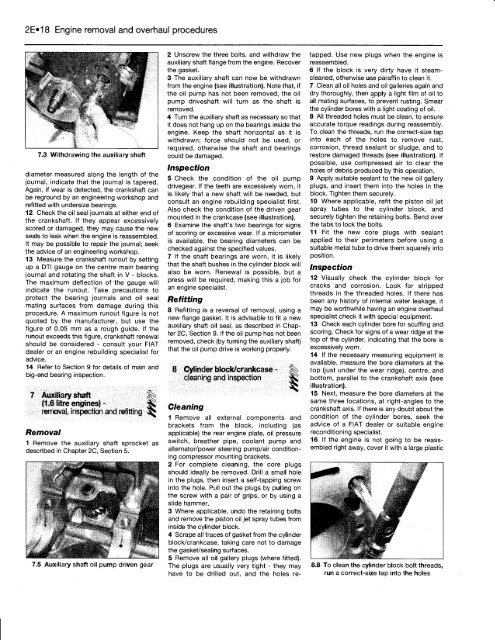
7.3 Withdrawing the auxiliary shaft<br />
diameter measured along the length of the<br />
journal, indicate that the journal is tapered.<br />
Again, if wear is detected, the crankshaft can<br />
be reground by an engineering workshop and<br />
refitted with undersize bearings.<br />
12 Check the oil seal journals at either end of<br />
the crankshaft. If they appear excessively<br />
scored or damaged, they may cause the new<br />
seals to leak when the engine is reassembled.<br />
It may be possible to repair the journal; seek<br />
the advice of an engineering workshop.<br />
13 Measure the crankshaft runout by setting<br />
up a DTI gauge on the centre main bearing<br />
journal and rotating the shaft in V - blocks.<br />
The maximum deflection of the gauge will<br />
indicate the runout. Take precautions to<br />
protect the bearing journals and oil seal<br />
mating surfaces from damage during this<br />
procedure. A maximum runout figure is not<br />
quoted by the manufacturer, but use the<br />
figure of 0.05 mm as a rough guide. If the<br />
runout exceeds this figure, crankshaft renewal<br />
should be considered - consult your FIAT<br />
dealer or an engine rebuilding specialist for<br />
advice.<br />
14 Refer to Section 9 for details of main and<br />
big-end bearing inspection.<br />
7 Auxiliary shaft §^<br />
(1.6 litre engines) -<br />
removal, inspection and refitting<br />
Removal<br />
1 Remove the auxiliary shaft sprocket as<br />
described in Chapter 2C, Section 5.<br />
7.5 Auxiliary shaft oil pump driven gear<br />
2 Unscrew the three bolts, and withdraw the<br />
auxiliary shaft flange from the engine. Recover<br />
the gasket.<br />
3 The auxiliary shaft can now be withdrawn<br />
from the engine (see illustration). Note that, if<br />
the oil pump has not been removed, the oil<br />
pump driveshaft will turn as the shaft is<br />
removed.<br />
4 Turn the auxiliary shaft as necessary so that<br />
it does not hang up on the bearings inside the<br />
engine. Keep the shaft horizontal as it is<br />
withdrawn; force should not be used, or<br />
required, otherwise the shaft and bearings<br />
could be damaged.<br />
Inspection<br />
5 Check the condition of the oil pump<br />
drivegear. If the teeth are excessively worn, it<br />
is likely that a new shaft will be needed, but<br />
consult an engine rebuilding specialist first.<br />
Also check the condition of the driven gear<br />
mounted in the crankcase (see illustration).<br />
6 Examine the shaft's two bearings for signs<br />
of scoring or excessive wear. If a micrometer<br />
is available, the bearing diameters can be<br />
checked against the specified values.<br />
7 If the shaft bearings are worn, it is likely<br />
that the shaft bushes in the cylinder block will<br />
also be worn. Renewal is possible, but a<br />
press will be required, making this a job for<br />
an engine specialist.<br />
Refitting<br />
8 Refitting is a reversal of removal, using a<br />
new flange gasket. It is advisable to fit a new<br />
auxiliary shaft oil seal, as described in Chapter<br />
2C, Section 9. If the oil pump has not been<br />
removed, check (by turning the auxiliary shaft)<br />
that the oil pump drive is working properly.<br />
8 Cylinder block/crankcase<br />
cleaning and inspection<br />
Cleaning<br />
1 Remove all external components and<br />
brackets from the block, including (as<br />
applicable) the rear engine plate, oil pressure<br />
switch, breather pipe, coolant pump and<br />
alternator/power steering pump/air conditioning<br />
compressor mounting brackets.<br />
2 For complete cleaning, the core plugs<br />
should ideally be removed. Drill a small hole<br />
in the plugs, then insert a self-tapping screw<br />
into the hole. Pull out the plugs by pulling on<br />
the screw with a pair of grips, or by using a<br />
slide hammer.<br />
3 Where applicable, undo the retaining bolts<br />
and remove the piston oil jet spray tubes from<br />
inside the cylinder block.<br />
4 Scrape all traces of gasket from the cylinder<br />
block/crankcase, taking care not to damage<br />
the gasket/sealing surfaces.<br />
5 Remove all oil gallery plugs (where fitted).<br />
The plugs are usually very tight - they may<br />
have to be drilled out, and the holes re-<br />
tapped. Use new plugs when the engine is<br />
reassembled.<br />
6 If the block is very dirty have it steamcleaned,<br />
otherwise use paraffin to clean it.<br />
7 Clean all oil holes and oil galleries again and<br />
dry thoroughly, then apply a light film of oil to<br />
all mating surfaces, to prevent rusting. Smear<br />
the cylinder bores with a light coating of oil.<br />
8 All threaded holes must be clean, to ensure<br />
accurate torque readings during reassembly.<br />
<strong>To</strong> clean the threads, run the correct-size tap<br />
into each of the holes to remove rust,<br />
corrosion, thread sealant or sludge, and to<br />
restore damaged threads (see illustration). If<br />
possible, use compressed air to clear the<br />
holes of debris produced by this operation.<br />
9 Apply suitable sealant to the new oil gallery<br />
plugs, and insert them into the holes in the<br />
block. Tighten them securely.<br />
10 Where applicable, refit the piston oil jet<br />
spray tubes to the cylinder block, and<br />
securely tighten the retaining bolts. Bend over<br />
the tabs to lock the bolts.<br />
11 Fit the new core plugs with sealant<br />
applied to their perimeters before using a<br />
suitable metal tube to drive them squarely into<br />
position.<br />
Inspection<br />
12 Visually check the cylinder block for<br />
cracks and corrosion. Look for stripped<br />
threads in the threaded holes. If there has<br />
been any history of internal water leakage, it<br />
may be worthwhile having an engine overhaul<br />
specialist check it with special equipment.<br />
13 Check each cylinder bore for scuffing and<br />
scoring. Check for signs of a wear ridge at the<br />
top of the cylinder, indicating that the bore is<br />
excessively worn.<br />
14 If the necessary measuring equipment is<br />
available, measure the bore diameters at the<br />
top (just under the wear ridge), centre, and<br />
bottom, parallel to the crankshaft axis (see<br />
illustration).<br />
15 Next, measure the bore diameters at the<br />
same three locations, at right-angles to the<br />
crankshaft axis. If there is any doubt about the<br />
condition of the cylinder bores, seek the<br />
advice of a FIAT dealer or suitable engine<br />
reconditioning specialist.<br />
16 If the engine is not going to be reassembled<br />
right away, cover it with a large plastic<br />
8.8 <strong>To</strong> clean the cylinder block bolt threads,<br />
run a correct-size tap into the holes


