

Bravo & Brava • 1995 To 2000
Bravo & Brava • 1995 To 2000
Bravo & Brava • 1995 To 2000

Create successful ePaper yourself
Turn your PDF publications into a flip-book with our unique Google optimized e-Paper software.
Refitting<br />
1.2 and 1.4 litre models and 1.6 litre<br />
models (automatic transmission)<br />
10 Before inserting the driveshaft, check the<br />
condition of the oil seal in the transmission<br />
casing, and if necessary renew it with reference<br />
to Chapter 7A or 7B. Briefly, the work involves<br />
unbolting the side flange, hooking out the old<br />
011 seal, then driving in the new oil seal using a<br />
suitable socket or metal tube on the hard outer<br />
surface, and finally refitting the flange.<br />
11 Carefully insert the inner end of the<br />
driveshaft so that it engages the splines of the<br />
differential gears, then press it firmly inwards<br />
until the circlip is felt to engage the groove in<br />
the gear.<br />
1.6 litre models (manual transmission)<br />
12 Before refitting the driveshaft, check the<br />
condition of the gaiter and if necessary renew<br />
it with reference to Section 3.<br />
13 Clean the flange on the side of the<br />
transmission, then insert the driveshaft inner<br />
joint tripod into the differential sun gear.<br />
Locate the gaiter on the transmission flange,<br />
and tighten the clip.<br />
1.8 litre models<br />
14 Clean the drive flange then locate the<br />
driveshaft inner joint on it and insert the bolts.<br />
Tighten the bolts securely in a progressive<br />
manner.<br />
All models<br />
15 Locate the outer end of the driveshaft in<br />
the splined hub and press in the top of the<br />
hub carrier.<br />
16 Engage the hub carrier with the bottom of<br />
the strut, then insert the bolts together with the<br />
spacers. The heads of the bolts face the rear<br />
of the car. Tighten the bolts to the specified<br />
torque.<br />
17 Reconnect the steering track-rod end with<br />
the hub carrier steering arm, then refit and<br />
tighten the nut. If the track-rod end stub turns<br />
in the steering arm, press down on it while<br />
tightening the nut.<br />
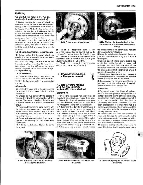
18 Screw on the new driveshaft (hub) nut and<br />
tighten it moderately at this stage (see<br />
illustration).<br />
19 Refit the roadwheel and lower the car to<br />
the ground.<br />
2.18 Fitting a new driveshaft nut<br />
20 Tighten the roadwheel bolts to the<br />
specified torque, then tighten the hub nut to<br />
the specified torque. Stake the rim of the hub<br />
nut into the machined recess in the end of the<br />
driveshaft using a hammer and punch (see<br />
illustrations). Refit the wheel trim.<br />
21 Check and top-up the transmission<br />
oil/fluid with reference to Chapter 1.<br />
3 Driveshaft overhaul and<br />
rubber gaiter renewal ^<br />
1.2 and 1.4 litre models<br />
and 1.6 litre models<br />
(automatic transmission)<br />
Dismantling<br />
1 Remove the driveshaft from the vehicle as<br />
described in Section 2, and mount it in a vice.<br />
2 Release the clips and move the gaiter away<br />
from the driveshaft inner joint housing. Slide<br />
the inner joint housing from the tripod joint.<br />
3 At the inboard end of the driveshaft, use a<br />
hammer and centre punch to mark the<br />
relationship between the shaft and tripod<br />
joint. Remove the circlip with a pair of circlip<br />
pliers, then using a three-legged puller if<br />
required, draw the tripod joint off the end of<br />
the driveshaft. Ensure that the legs of the<br />
puller bear upon the cast centre section of the<br />
joint, not the roller bearings (see illustration).<br />
4 At the outer end of the driveshaft, release<br />
Driveshafts 8»3<br />
2.20a Tighten the driveshaft nut to the<br />
specified torque (roadwheel removed for<br />
clarity)<br />
the clips and move the gaiter away from the<br />
driveshaft outer joint housing.<br />
5 Mark the relationship between the outer<br />
joint and the driveshaft using a scriber or a<br />
dab of paint.<br />
6 Using a pair of circlip pliers, expand the<br />
circlip that holds the joint in place and<br />
withdraw the joint from the end of the<br />
driveshaft. Note that the circlip is captive in<br />
the joint, and need not be removed, unless it<br />
appears damaged or worn.<br />
7 Slide both rubber gaiters off the driveshaft. It<br />
is recommended that the gaiters are renewed<br />
whenever removed from the driveshaft.<br />
8 If necessary, the damping weight may be<br />
removed from the right-hand driveshaft,<br />
however note its fitted position first.<br />
Inspection<br />
9 Thoroughly clean the driveshaft splines,<br />
and CV joint components with paraffin or a<br />
suitable solvent, taking care not to destroy<br />
any alignment marks made during removal. It<br />
is not recommended that the joint is<br />
completely dismantled, however, if it falls<br />
apart accidentally, it is important that it is<br />
correctly reassembled. The small webs of the<br />
hub must align with the large webs of the<br />
housing, and vice versa.<br />
10 Examine the CV joint components for<br />
wear and damage. In particular, check the<br />
balls and corresponding grooves for pitting<br />
and corrosion. If evidence of wear is visible,<br />
then the joint must be renewed.<br />
11 Examine the tripod joint components for<br />
wear. Check that the three rollers are free to<br />
2.20b Stake the rim of the nut into the 2.20c Recess machined into end of the 3.3 Draw the tripod joint off the end of the<br />
recess in the driveshaft driveshaft driveshaft


