

Bravo & Brava • 1995 To 2000
Bravo & Brava • 1995 To 2000
Bravo & Brava • 1995 To 2000

Create successful ePaper yourself
Turn your PDF publications into a flip-book with our unique Google optimized e-Paper software.
8*2 Driveshafts<br />
1 General information<br />
Power is transmitted from the differential to<br />
the roadwheels by the driveshafts, via inboard<br />
and outboard constant velocity (CV) joints.<br />
An intermediate shaft, with its own support<br />
bearing is fitted between the transmission<br />
output and right-hand driveshaft on 1.8 litre<br />
models. This has the effect of equalising<br />
driveshaft angles at all suspension positions<br />
and reduces driveshaft flexing, which<br />
improves directional stability, particularly<br />
under acceleration.<br />
The outer Rzeppa type CV joints allow<br />
smooth transmission of drive to the wheels at<br />
all steering and suspension angles. Drive is<br />
transmitted by means of a number of steel<br />
balls that run in grooves between the two<br />
halves of the joint.<br />
On 1.2 and 1.4 litre models, and 1.6 litre<br />
automatic transmission models, the inboard<br />
CV joint is of tripod type; drive is transmitted<br />
across the joint by means of three rollers,<br />
mounted on the driveshaft in a tripod<br />
arrangement, which is free to slide in the<br />
grooved cup. On 1.6 litre models with<br />
manual transmission, the inboard CV joint is<br />
similar to that of the 1.2 and 1.4 litre models,<br />
except that the tripod and rollers are located<br />
directly in the differential sun gears, and the<br />
rubber gaiters do not rotate with the driveshaft.<br />
The gaiters are secured to the transmission<br />
side flanges by clips. On 1.8 litre<br />
models, the inboard CV joints are of constant<br />
velocity type, like the outer joints, and are<br />
bolted to drive flanges on the left-hand side<br />
of the transmission and on the right-hand<br />
end of the intermediate shaft.<br />
The joint rubber gaiters are packed with<br />
grease, to provide permanent lubrication. If<br />
wear is detected in the joint, it can be<br />
detached from the driveshaft and renewed.<br />
Normally, the CV joints do not require<br />
additional lubrication, unless they have been<br />
overhauled or the rubber gaiters have been<br />
damaged, allowing the grease to become<br />
contaminated. Refer to Chapter 1, Section 10,<br />
for guidance on checking the condition of the<br />
driveshaft gaiters.<br />
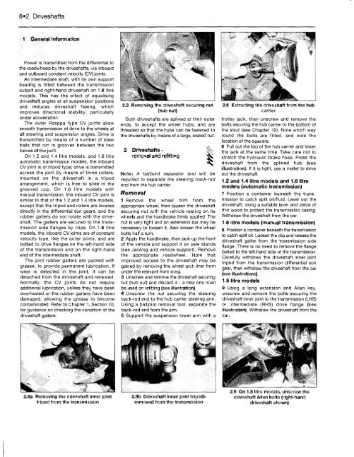
2.8a Removing the driveshaft inner joint<br />
tripod from the transmission<br />
2.3 Removing the driveshaft securing nut<br />
(hub nut)<br />
Both driveshafts are splined at their outer<br />
ends, to accept the wheel hubs, and are<br />
threaded so that the hubs can be fastened to<br />
the driveshafts by means of a large, staked nut.<br />
2 Driveshafts -<br />
removal and refitting<br />
Note: A balljoint separator tool will be<br />
required to separate the steering track-rod<br />
end from the hub carrier.<br />
Removal<br />
1 Remove the wheel trim from the<br />
appropriate wheel, then loosen the driveshaft<br />
securing nut with the vehicle resting on its<br />
wheels and the handbrake firmly applied. The<br />
nut is very tight and an extension bar may be<br />
necessary to loosen it. Also loosen the wheel<br />
bolts half a turn.<br />
2 Apply the handbrake, then jack up the front<br />
of the vehicle and support it on axle stands<br />
(see Jacking and vehicle support). Remove<br />
the appropriate roadwheel. Note that<br />
improved access to the driveshaft may be<br />
gained by removing the wheel arch liner from<br />
under the relevant front wing.<br />
3 Unscrew and remove the driveshaft securing<br />
nut (hub nut) and discard it - a new one must<br />
be used on refitting (see illustration).<br />
4 Unscrew the nut securing the steering<br />
track-rod end to the hub carrier steering arm.<br />
Using a balljoint removal tool, separate the<br />
track-rod end from the arm.<br />
5 Support the suspension lower arm with a<br />
2.8b Driveshaft inner joint tripods<br />
removed from the transmission<br />
2.6 Extracting the driveshaft from the hub<br />
carrier<br />
trolley jack, then unscrew and remove the<br />
bolts securing the hub carrier to the bottom of<br />
the strut (see Chapter 10). Note which way<br />
round the bolts are fitted, and note the<br />
location of the spacers.<br />
6 Pull out the top of the hub carrier and lower<br />
the jack at the same time. Take care not to<br />
stretch the hydraulic brake hose. Press the<br />
driveshaft from the splined hub (see<br />
illustration). If it is tight, use a mallet to drive<br />
out the driveshaft.<br />
1.2 and 1.4 litre models and 1.6 litre<br />
models (automatic transmission)<br />
7 Position a container beneath the transmission<br />
to catch spilt oil/fluid. Lever out the<br />
driveshaft, using a suitable lever and piece of<br />
thin wood to protect the transmission casing.<br />
Withdraw the driveshaft from the car.<br />
1.6 litre models (manual transmission)<br />
8 Position a container beneath the transmission<br />
to catch spilt oil. Loosen the clip and release the<br />
driveshaft gaiter from the transmission side<br />
flange. There is no need to remove the flange<br />
bolted to the left-hand side of the transmission.<br />
Carefully withdraw the driveshaft inner joint<br />
tripod from the transmission differential sun<br />
gear, then withdraw the driveshaft from the car<br />
(see illustrations).<br />
1.8 litre models<br />
9 Using a long extension and Allen key,<br />
unscrew and remove the bolts securing the<br />
driveshaft inner joint to the transmission (LHS)<br />
or intermediate (RHS) drive flange (see<br />
illustration). Withdraw the driveshaft from the<br />
car.<br />
2.9 On 1.8 litre models, unscrew the<br />
driveshaft Allen bolts (right-hand<br />
driveshaft shown)


