

Bravo & Brava • 1995 To 2000
Bravo & Brava • 1995 To 2000
Bravo & Brava • 1995 To 2000

Create successful ePaper yourself
Turn your PDF publications into a flip-book with our unique Google optimized e-Paper software.
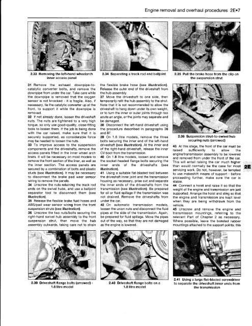
2.33 Removing the left-hand wheelarch<br />
inner access panel<br />
31 Remove the exhaust downpipe-tocatalytic<br />
converter bolts, and remove the<br />
downpipe from under the car. Take care while<br />
the downpipe is removed that the oxygen<br />
sensor is not knocked - it is fragile. Also, if<br />
necessary, tie the catalytic converter up at the<br />
front, to support it while the downpipe is<br />
removed.<br />
32 If not already done, loosen the driveshaft<br />
nuts. The nuts are tightened to a very high<br />
torque, so only use good-quality, close-fitting<br />
tools to loosen them. If the job is being done<br />
with the car raised, make sure that it is<br />
securely supported, as considerable force<br />
may be needed to loosen the nuts.<br />
33 <strong>To</strong> improve access to the suspension<br />
components and the driveshafts, remove the<br />
access panels fitted in the inner wheel arch<br />
liners. It will be necessary on most models to<br />
remove the front section of the liner, as well as<br />
the inner section. The access panels are<br />
secured by a combination of bolts and plastic<br />
studs (see illustration). It may be necessary<br />
to disconnect the brake pad wear sensor<br />
wiring to remove the panels.<br />
34 Unscrew the nuts retaining the track rod<br />
ends on the swivel hubs, and use a balljoint<br />
separator tool to disconnect them (see<br />
illustration).<br />
35 Release the flexible brake fluid hoses and<br />
ABS/pad wear sensor wiring from the front<br />
suspension struts (see illustration).<br />
36 Unscrew the two nuts/bolts securing the<br />
right-hand swivel hub assembly to the front<br />
suspension strut, then move the hub<br />
assembly outwards, taking care not to strain<br />
2.39 Driveshaft flange bolts (arrowed) <strong>•</strong><br />
1.6 litre model<br />
2.34 Separating a track rod end balljoint<br />
the flexible brake hose (see illustration).<br />
Release the outer end of the driveshaft from<br />
the hub assembly.<br />
37 Move the driveshaft to one side, then<br />
temporarily refit the hub assembly to the strut.<br />
Note that it is not recommended to allow the<br />
driveshaft to hang down under its own weight,<br />
or to turn the inner or outer joints through too<br />
acute an angle, or the joints may separate and<br />
be damaged.<br />
38 Disconnect the left-hand driveshaft using<br />
the procedure described in paragraphs 36<br />
and 37.<br />
39 On 1.6 litre models, remove the three<br />
bolts securing the inner end of the left-hand<br />
driveshaft (see illustration). At the inner end<br />
of the right-hand driveshaft, release the inner<br />
CV boot from the transmission.<br />
40 On 1.8 litre models, loosen and remove<br />
the socket-headed flange bolts securing the<br />
inner ends of the driveshafts (see<br />
illustration).<br />
41 Using a suitable flat-bladed tool between<br />
the driveshaft inner joint and the transmission<br />
housing as necessary, prise out and separate<br />
the inner ends of the driveshafts from the<br />
transmission (see illustration). Be prepared<br />
for oil or fluid spillage if the transmission was<br />
not drained. Remove the driveshafts from<br />
under the car.<br />
42 On automatic transmission models,<br />
loosen the union nuts and disconnect the fluid<br />
pipes at the side of the transmission. Again,<br />
be prepared for fluid spillage. Move the pipes<br />
out of the way, so that they are not damaged<br />
as the engine is lowered.<br />
2.40 Driveshaft flange bolts on a<br />
1.8 litre model<br />
Engine removal and overhaul procedures 2E»7<br />
2.35 Pull the brake hose from the clip on<br />
the suspension strut<br />
2.36 Suspension strut-to-swivel hub<br />
securing nuts (arrowed)<br />
43 At this stage, the front of the car must be<br />
raised sufficiently to allow the<br />
engine/transmission assembly to be lowered<br />
and removed from under the front of the car.<br />
This will entail raising the car much higher<br />
than would normally be the case for most<br />
servicing work. Do not, however, be tempted<br />
to use makeshift means of support - before<br />
proceeding further, make sure the car is<br />
stable.<br />
44 Connect a hoist and raise it so that the<br />
weight of the engine and transmission are just<br />
supported. Arrange the hoist and sling so that<br />
the engine and transmission are kept level<br />
when they are being withdrawn from the<br />
vehicle.<br />
45 Unscrew and remove the engine and<br />
transmission mountings, referring to the<br />
relevant Part of Chapter 2 as necessary.<br />
Where possible, leave the bonded rubber<br />
mountings attached to the support points; this<br />
2.41 Using a large flat-bladed screwdriver<br />
to separate the driveshaft inner ends from<br />
the transmission


