

Bravo & Brava • 1995 To 2000
Bravo & Brava • 1995 To 2000
Bravo & Brava • 1995 To 2000

You also want an ePaper? Increase the reach of your titles
YUMPU automatically turns print PDFs into web optimized ePapers that Google loves.
4B»10 Fuel system - multi-point injection<br />
4.75 Camshaft position sensor location<br />
and securing bolts -1.8 litre model<br />
1.8 litre models<br />
74 Remove the timing belt and exhaust camshaft<br />
sprocket as described in Chapter 2D,<br />
Sections 4 and 5.<br />
75 Remove the two bolts securing the sensor<br />
(see illustration). Withdraw the sensor from the<br />
engine, and disconnect the wiring plug at the<br />
rear of the timing belt cover.<br />
76 Refitting is a reversal of removal.<br />
Vehicle speed (speedometer)<br />
sensor<br />
77 Refer to the information given in Chapter<br />
4A, Section 5.<br />
5 Fuel pump/ fk<br />
fuel gauge sender unit - S£<br />
removal and refitting 3^<br />
Removal<br />
Note: Refer to the precautions in Section 1<br />
before proceeding.<br />
1 Disconnect the negative cable from the<br />
battery terminal.<br />
2 Remove the press stud fixings and detach<br />
the carpet from the load space floor.<br />
5.6 Disconnecting the fuel tank breather<br />
pipe<br />
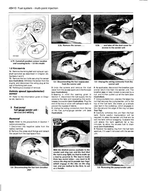
5.3a Remove the screws ...<br />
5.4 Disconnecting the fuel supply pipe<br />
from the sender unit<br />
3 Undo the screws and remove the dust<br />
cover from the access aperture in the floorpan<br />
(see illustrations).<br />
4 Bearing in mind the warning given in<br />
Section 1, disconnect the fuel supply line by<br />
pressing the tabs and separating the quickrelease<br />
connection (see illustration). Plug the<br />
end of the line or cover with adhesive tape, to<br />
prevent the ingress of debris.<br />
5 Unplug the wiring connectors from the top<br />
of the fuel pump/gauge sender unit (see<br />
illustration).<br />
With the limited access available to the<br />
sender unit ring nut, and the fact that<br />
the nut is very tight, we had to make up<br />
a tool to unscrew it. The tool is made<br />
from two metal strips - one bent to fit<br />
across the ring nut to provide two 'legs'<br />
which engage in the ribs on the ring<br />
nut, and one bolted to the first, to act<br />
as a handle.<br />
5.5 Unplug the wiring connector from the<br />
sender unit<br />
6 As applicable, disconnect the breather pipe<br />
and/or return line from the sender unit. The<br />
breather pipe on later models is secured by a<br />
nut, and is then pulled out of the tank (see<br />
illustration).<br />
7 Using a suitable tool, unscrew the large ring<br />
nut that secures the pump/sender unit to the<br />
top of the fuel tank. We made up a simple<br />
claw tool in the workshop, which engages in<br />
the ribs around the edge of the ring nut (see<br />
<strong>To</strong>ol Tip)<br />
8 Carefully withdraw the unit from the fuel<br />
tank. Some careful manipulation will be<br />
required, to allow the sender unit float arm to<br />
exit the tank without snagging. Suspend the<br />
unit above the tank aperture for a few<br />
minutes, to allow the excess fuel to drain<br />
away (see illustration).<br />
9 Recover the sealing ring from the fuel tank<br />
aperture, if it wasn't removed with the sender<br />
unit.<br />
5.8 Removing the pump/sender unit


