

Bravo & Brava • 1995 To 2000
Bravo & Brava • 1995 To 2000
Bravo & Brava • 1995 To 2000

You also want an ePaper? Increase the reach of your titles
YUMPU automatically turns print PDFs into web optimized ePapers that Google loves.
29 Loosen the power steering pump pulley<br />
bolts.<br />
30 Remove the fasteners and remove the<br />
wheel arch liner from the right-hand side.<br />
31 Remove the auxiliary drivebelt with<br />
reference to Chapter 1.<br />
32 Fully unscrew the bolts and remove the<br />
pulley from the pump.<br />
33 Unbolt the engine support mounting link<br />
from the right-hand side of the engine, then<br />
unbolt the link bracket from the body.<br />
34 Disconnect the wiring connector and<br />
earth wire from over the power steering pump.<br />
35 Loosen the clip and disconnect the<br />
reservoir hose from the pump. Position a<br />
suitable container beneath the pump to catch<br />
spilled fluid.<br />
36 Unscrew the union nut and disconnect the<br />
steering gear pressure supply line from the<br />
pump.<br />
37 Working beneath the car, unbolt the inlet<br />
manifold support bracket from the rear of the<br />
engine.<br />
38 Unbolt the alternator mounting bracket<br />
from the rear of the engine.<br />
39 Unscrew the mounting bolts and remove<br />
the pump.<br />
Refitting<br />
40 Refitting is a reversal of removal, but<br />
tighten the nuts and bolts to the specified<br />
torque where given. Refill the hydraulic<br />
system with the specified grade and quantity<br />
of power steering fluid, then bleed the<br />
hydraulic system as described in Section 21.<br />
Adjust the tension of the power steering pump<br />
drivebelt as described in Chapter 1.<br />
23 Track-rod end -<br />
removal and refitting<br />
Removal<br />
Note: A balljoint separator tool will be<br />
required for this operation. A new track-rod<br />
end nut split pin should be used on refitting.<br />
1 Apply the handbrake, then jack up the front<br />
of the vehicle and support it on axle stands<br />
(see Jacking and vehicle support). Remove<br />
the relevant front roadwheel.<br />
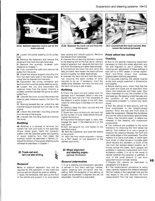
2 Unscrew the nut securing the track-rod end<br />
to the steering arm on'the hub carrier. Using a<br />
balljoint separator tool, separate the track-rod<br />
end from the steering arm (see illustrations).<br />
3 Counterhold the track-rod end using the<br />
flats provided, then loosen the track-rod end<br />
locknut a quarter turn (see illustration).<br />
4 Unscrew the track-rod end from the trackrod,<br />
counting the exact number of turns<br />
required to do so. !f necessary, mark the<br />
relationship between the track-rod end and<br />
the track-rod using a dab of paint.<br />
Refitting<br />
5 Check the track-rod end rubber boot for<br />
damage, and if necessary obtain a new one.<br />
Renew the track-rod end if the movement of<br />
the balljoint is either sloppy or too stiff. Also<br />
check for other signs of damage such as worn<br />
threads.<br />
6 Carefully clean the track-rod end and the<br />
track-rod threads.<br />
7 Screw the track-rod end onto the track-rod<br />
by the number of turns noted before removal.<br />
Tighten the locknut.<br />
8 Ensure that the balijoint taper is clean, then<br />
engage the taper in the steering arm on the<br />
hub carrier.<br />
9 Refit the balljoint nut, and tighten to the<br />
specified torque.<br />
10 Refit the roadwheel, and lower the vehicle<br />
to the ground.<br />
11 Have the front wheel alignment checked<br />
by a FIAT deale r or tyre specialist at the<br />
earliest opportunity.<br />
24 Wheel alignment<br />
and steering angles -<br />
general information<br />
General information<br />
1 A car's steering and suspension geometry<br />
is defined in four basic settings; camber,<br />
castor, steering axis inclination, and toesetting.<br />
With the exception of toe setting, all<br />
angles are expressed in degrees and are not<br />
adjustable. <strong>To</strong>e-setting is adjustable.<br />
Suspension and steering systems 10*13<br />
Front wheel toe setting<br />
Checking<br />
2 Due to the special measuring equipment<br />
necessary to check the wheel alignment, and<br />
the skill required to use it properly, the<br />
checking and adjustment of these settings is<br />
best left to a FIAT dealer or similar expert.<br />
Most tyre-fitting shops now possess<br />
sophisticated checking equipment.<br />
3 For accurate checking, the vehicle must be<br />
at the kerb weight specified in Dimensions<br />
and weights.<br />
4 Before starting work, check first that the<br />
tyre sizes and types are as specified, then<br />
check tyre pressures and tread wear. Also<br />
check roadwheel run-out, the condition of the<br />
hub bearings, the steering wheel free play and<br />
the condition of the front suspension<br />
components (Chapter 1). Correct any faults<br />
found.<br />
5 Park the vehicle on level ground, with the<br />
front roadwheels in the straight-ahead<br />
position. Rock the rear and front ends to<br />
settle the suspension. Release the handbrake<br />
and roll the vehicle backwards approximately<br />
1 metre, then forwards again, to relieve any<br />
stresses in the steering and suspension<br />
components.<br />
6 Two methods are available to the home<br />
mechanic for checking the front wheel toe<br />
setting. One method is to use a gauge to<br />
measure the distance between the front and<br />
rear inside edges of the roadwheels. The other<br />
method is to use a scuff plate, in which each<br />
front wheel is rolled across a movable plate<br />
which records any deviation, or scuff, of the<br />
tyre from the straight-ahead position as it<br />
moves across the plate. Such gauges are<br />
available in relatively-inexpensive form from<br />
accessory outlets. It is up to the owner to<br />
decide whether the expense is justified, in<br />
view of the small amount of use such<br />
equipment would normally receive.<br />
7 Prepare the vehicle as described in<br />
paragraphs 3 to 5 above.<br />
8 If the measurement procedure is being<br />
used, carefully measure the distance between<br />
the front edges of the roadwheel rims and the<br />
rear edges of the rims. Subtract the front<br />
measurement from the rear measurement,


