

Bravo & Brava • 1995 To 2000
Bravo & Brava • 1995 To 2000
Bravo & Brava • 1995 To 2000

Create successful ePaper yourself
Turn your PDF publications into a flip-book with our unique Google optimized e-Paper software.
4A»4 Fuel system - single-point injection<br />
4.5 Removing the fuse panel cover 4.7 Accelerator cable guide securing nut<br />
(arrowed)<br />
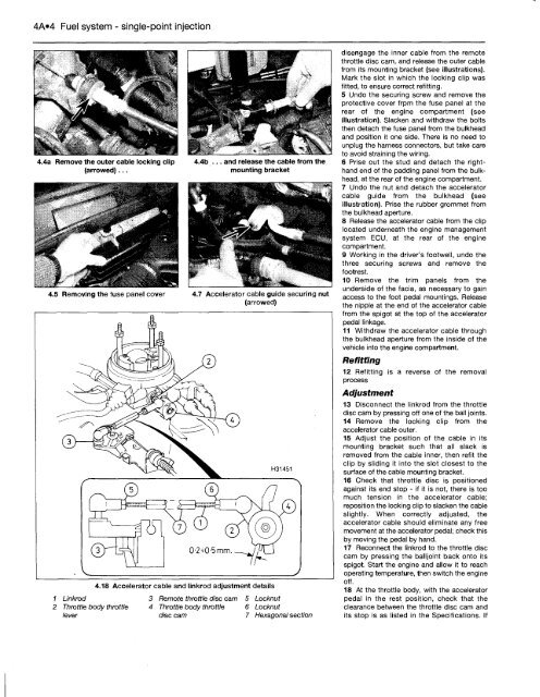
4.18 Accelerator cable and linkrod adjustment details<br />
1 Linkrod 3 Remote throttle disc cam 5 Locknut<br />
2 Throttle body throttle 4 Throttle body throttle 6 Locknut<br />
lever disc cam 7 Hexagonal section<br />
disengage the inner cable from the remote<br />
throttle disc cam, and release the outer cable<br />
from its mounting bracket (see illustrations).<br />
Mark the slot in which the locking clip was<br />
fitted, to ensure correct refitting.<br />
5 Undo the securing screw and remove the<br />
protective cover frpm the fuse panel at the<br />
rear of the engine compartment (see<br />
illustration). Slacken and withdraw the bolts<br />
then detach the fuse panel from the bulkhead<br />
and position it one side. There is no need to<br />
unplug the harness connectors, but take care<br />
to avoid straining the wiring.<br />
6 Prise out the stud and detach the righthand<br />
end of the padding panel from the bulkhead,<br />
at the rear of the engine compartment.<br />
7 Undo the nut and detach the accelerator<br />
cable guide from the bulkhead (see<br />
illustration). Prise the rubber grommet from<br />
the bulkhead aperture.<br />
8 Release the accelerator cable from the clip<br />
located underneath the engine management<br />
system ECU, at the rear of the engine<br />
compartment.<br />
9 Working in the driver's footwell, undo the<br />
three securing screws and remove the<br />
footrest.<br />
10 Remove the trim panels from the<br />
underside of the facia, as necessary to gain<br />
access to the foot pedal mountings. Release<br />
the nipple at the end of the accelerator cable<br />
from the spigot at the top of the accelerator<br />
pedal linkage.<br />
11 Withdraw the accelerator cable through<br />
the bulkhead aperture from the inside of the<br />
vehicle into the engine compartment.<br />
Refitting<br />
12 Refitting is a reverse of the removal<br />
process<br />
Adjustment<br />
13 Disconnect the linkrod from the throttle<br />
disc cam by pressing off one of the ball joints.<br />
14 Remove the locking clip from the<br />
accelerator cable outer.<br />
15 Adjust the position of the cable in its<br />
mounting bracket such that all slack is<br />
removed from the cable inner, then refit the<br />
clip by sliding it into the slot closest to the<br />
surface of the cable mounting bracket.<br />
16 Check that throttle disc is positioned<br />
against its end stop - if it is not, there is too<br />
much tension in the accelerator cable;<br />
reposition the locking clip to slacken the cable<br />
slightly. When correctly adjusted, the<br />
accelerator cable should eliminate any free<br />
movement at the accelerator pedal; check this<br />
by moving the pedal by hand.<br />
17 Reconnect the linkrod to the throttle disc<br />
cam by pressing the balljoint back onto its<br />
spigot. Start the engine and allow it to reach<br />
operating temperature, then switch the engine<br />
off.<br />
18 At the throttle body, with the accelerator<br />
pedal in the rest position, check that the<br />
clearance between the throttle disc cam and<br />
its stop is as listed in the Specifications. If


