

Bravo & Brava • 1995 To 2000
Bravo & Brava • 1995 To 2000
Bravo & Brava • 1995 To 2000

You also want an ePaper? Increase the reach of your titles
YUMPU automatically turns print PDFs into web optimized ePapers that Google loves.
S§^)/ H31468<br />
6.11 Selector lever position sensor<br />
3 Remove the battery and battery tray with<br />
reference to Chapter 5A.<br />
4 Release the wiring from the rear of the<br />
battery mounting bracket, then undo the bolt<br />
and remove the relay box cover. Unscrew the<br />
nuts and remove the relay box from the<br />
mounting bracket - position the box to one<br />
side.<br />
5 Disconnect the wiring from the engine<br />
management ECU by unclipping the<br />
connector. Unscrew the nuts and remove the<br />
ECU mounting bracket from the battery<br />
mounting bracket. The nuts also secure the<br />
starter motor and fuel injection wiring.<br />
6 Unbolt and remove the battery mounting<br />
bracket and unclip the remaining wiring<br />
supports.<br />
7 Remove the spring clip and washer, and<br />
disconnect the selector cable end from the<br />
lever on the transmission.<br />
8 Disconnect the selector lever position<br />
sensor wiring at the connector.<br />
9 Unscrew the nut and remove the lever from<br />
the sensor.<br />
10 Release the special washer from the<br />
central nut, then unscrew and remove the nut.<br />
11 Unscrew the mounting bolts and remove<br />
the selector lever position sensor from the<br />
transmission (see illustration).<br />
Refitting<br />
12 Locate the sensor on the spindle followed<br />
by the special washer, then tighten the nut<br />
securely and bend up the washer tabs to lock.<br />
13 Insert and tighten the mounting bolts<br />
securely.<br />
14 With the sensor adjustment bolts loose,<br />
turn the spindle fully clockwise to position P,<br />
then turn it two notches anticlockwise to<br />
position N.<br />
15 Turn the sensor until the projection on its<br />
upper surface is aligned with the machined<br />
edges on the spindle (see illustration).<br />
Tighten the sensor adjustment bolts without<br />
moving the sensor.<br />
16 An alternative method of setting the<br />
sensor is to use an ohmmeter. Connect the<br />
ohmmeter between terminals 6 and 10 of the<br />
wiring connector then turn the sensor to<br />
determine the limits of the arc where the<br />
meter indicates continuity. Position the sensor<br />
in the centre of this arc, then tighten the<br />
adjustment bolts. The N and P internal<br />
6.15 Turn the sensor until the projection<br />
on its upper surface (1) is aligned with the<br />
machined edges on the spindle (2)<br />
contacts are both closed with the sensor in its<br />
centre position.<br />
17 Refit the lever to the spindle and tighten<br />
the nut.<br />
18 Reconnect the wiring.<br />
19 Refer to Section 4 when refitting the<br />
selector cable.<br />
20 The remaining procedure is a reversal of<br />
removal.<br />
7 Electronic control unit -<br />
removal and refitting >jk<br />
Caution: Handle the electronic control unit<br />
carefully, and do not touch the connector<br />
terminals. Do not attempt to remove the<br />
cover from the unit.<br />
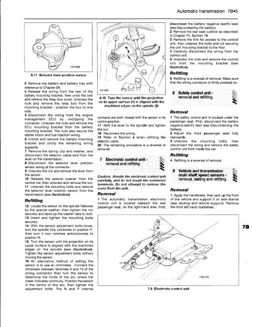
Removal<br />
1 The automatic transmission electronic<br />
control unit is located beneath the rear<br />
passenger seat, on the right-hand side. First,<br />
Automatic transmission 7B«5<br />
disconnect the battery negative (earth) lead<br />
(see Disconnecting the battery).<br />
2 Remove the rear seat cushion as described<br />
in Chapter 11, Section 19.<br />
3 Remove the trim for access to the control<br />
unit, then unscrew the bolts and nut securing<br />
the unit mounting bracket to the floor.<br />
4 Carefully disconnect the wiring from the<br />
control unit.<br />
5 Unscrew the nuts and remove the control<br />
unit from the mounting bracket (see<br />
illustration).<br />
Refitting<br />
6 Refitting is a reversal of removal. Make sure<br />
that the wiring connector is firmly pressed on.<br />
8 Safety control unit - |§<br />
removal and refitting |k<br />
Removal<br />
1 The safety control unit is located under the<br />
passenger seat. First, disconnect the battery<br />
negative (earth) lead (see Disconnecting the<br />
battery).<br />
2 Adjust the front passenger seat fully<br />
rearwards.<br />
3 Unscrew the mounting bolts, then<br />
disconnect the wiring and remove the safety<br />
control unit from inside the car.<br />
Refitting<br />
4 Refitting is a reversal of removal.<br />
9 Vehicle and transmission ||=<br />
main shaft speed sensors -<br />
removal, testing and refitting 3Q<br />
Removal<br />
7.5 Electronic control unit<br />
1 Apply the handbrake, then jack up the front<br />
of the vehicle and support it on axle stands<br />
(see Jacking and vehicle support). Remove<br />
the front left-hand roadwheel.


