

Bravo & Brava • 1995 To 2000
Bravo & Brava • 1995 To 2000
Bravo & Brava • 1995 To 2000

Create successful ePaper yourself
Turn your PDF publications into a flip-book with our unique Google optimized e-Paper software.
2E»16 Engine removal and overhaul procedures<br />
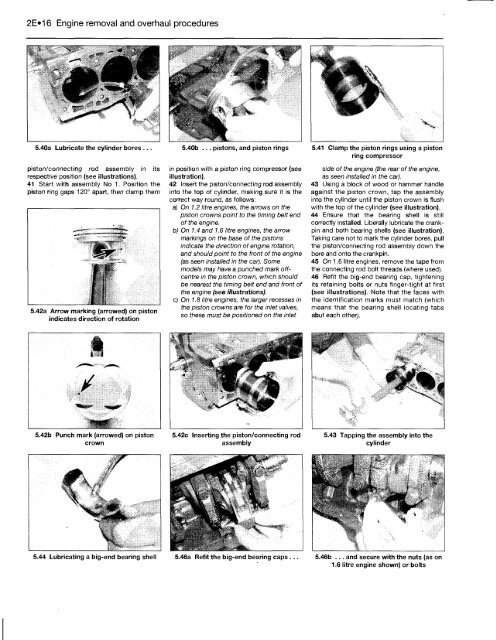
5.40a Lubricate the cylinder bores ...<br />
piston/connecting rod assembly in its<br />
respective position (see illustrations).<br />
41 Start with assembly No 1. Position the<br />
piston ring gaps 120° apart, then clamp them<br />
5.42a Arrow marking (arrowed) on piston<br />
indicates direction of rotation<br />
5.42b Punch mark (arrowed) on piston<br />
crown<br />
5.44 Lubricating a big-end bearing shell<br />
5.40b ... pistons, and piston rings<br />
in position with a piston ring compressor (see<br />
illustration).<br />
42 Insert the piston/connecting rod assembly<br />
into the top of cylinder, making sure it is the<br />
correct way round, as follows:<br />
a) On 1.2 litre engines, the arrows on the<br />
piston crowns point to the timing belt end<br />
of the engine.<br />
b) On 1.4 and 1.6 litre engines, the arrow<br />
markings on the base of the pistons<br />
indicate the direction of engine rotation,<br />
and should point to the front of the engine<br />
(as seen installed in the car). Some<br />
models may have a punched mark offcentre<br />
in the piston crown, which should<br />
be nearest the timing belt end and front of<br />
the engine (see illustrations).<br />
c) On 1.8 litre engines, the larger recesses in<br />
the piston crowns are for the inlet valves,<br />
so these must be positioned on the inlet<br />
5.42c Inserting the piston/connecting rod<br />
assembly<br />
5.46a Refit the big-end bearing caps ...<br />
5.41 Clamp the piston rings using a piston<br />
ring compressor<br />
side of the engine (the rear of the engine,<br />
as seen installed in the car).<br />
43 Using a block of wood or hammer handle<br />
against the piston crown, tap the assembly<br />
into the cylinder until the piston crown is flush<br />
with the top of the cylinder (see illustration).<br />
44 Ensure that the bearing shell is still<br />
correctly installed. Liberally lubricate the crankpin<br />
and both bearing shells (see illustration).<br />
Taking care not to mark the cylinder bores, pull<br />
the piston/connecting rod assembly down the<br />
bore and onto the crankpin.<br />
45 On 1.6 litre engines, remove the tape from<br />
the connecting rod bolt threads (where used).<br />
46 Refit the big-end bearing cap, tightening<br />
its retaining bolts or nuts finger-tight at first<br />
(see illustrations). Note that the faces with<br />
the identification marks must match (which<br />
means that the bearing shell locating tabs<br />
abut each other).<br />
5.43 Tapping the assembly into the<br />
cylinder<br />
5.46b ... and secure with the nuts (as on<br />
1.6 litre engine shown) or bolts


