

Bravo & Brava • 1995 To 2000
Bravo & Brava • 1995 To 2000
Bravo & Brava • 1995 To 2000

You also want an ePaper? Increase the reach of your titles
YUMPU automatically turns print PDFs into web optimized ePapers that Google loves.
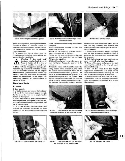
20.11 Removing the door kick-panels<br />
inertia reel in position, holding the front seat<br />
occupants firmly in position. Once the<br />
tensioner has been triggered, the seat belt will<br />
be permanently locked and the assembly<br />
must be renewed.<br />
3 <strong>To</strong> prevent the risk of injury, note the<br />
following warnings before contemplating any<br />
work on the front seat belts.<br />
A<br />
Warning: If the seat belt/<br />
tensioner mechanism is dropped<br />
from a height of 1 metre or<br />
more, it must be renewed, even<br />
if it has suffered no apparent damage. Do<br />
not allow any solvents to come into contact<br />
with the tensioner cylinder. Do not subject<br />
the tensioner cylinder/inertia reel to any<br />
form of shock as this could accidentally<br />
trigger the mechanism. Do not subject the<br />
tensioner cylinder to temperatures in<br />
excess of 110°C<br />
Front seat belts<br />
Removal<br />
3-door models<br />
1 Undo the screws and remove the front door<br />
kick-panel. The front screw is located beneath<br />
the facia and the rear one is located at the<br />
bottom of the B-pillar.<br />
2 At the base of the B-pillar undo the screw<br />
securing the trim, then prise off the covers,<br />
and unscrew the bolts securing the seat belt<br />
rail to the side panel.<br />
3 On models with ABS, remove the rear seat<br />
cushion as described in Section 19, then<br />
disconnect the wiring leading to the rear ABS<br />
sensor.<br />
20.12 Pull the door weatherstrips away<br />
from the B-pillar<br />
4 Pull out the door weatherstrip from the rear<br />
side panel.<br />
5 Undo the screws securing the rear side<br />
panel to the sill panel.<br />
6 Prise off the cover and unscrew the bolt<br />
securing the seat belt to the floor.<br />
7 Prise out the covers and unscrew the side<br />
trim screws. Also unbolt the rear seat lock.<br />
Withdraw the side trim.<br />
8 Extract the clip and remove the guide pin<br />
from the B-pillar. Release the seat belt at the<br />
same time.<br />
9 Break the plastic protective collar around the<br />
safety bracket with a screwdriver, and unbolt<br />
the bracket from the tensioner. Note: This will<br />
invalidate the manufacturer's guarantee. The<br />
bolt is of double-headed shear type and must<br />
be renewed together with the bracket. Note<br />
that as the bracket is removed, the tensioner<br />
will be locked to prevent accidental activation.<br />
10 Unscrew the mounting bolt and withdraw<br />
20.13b ... and unscrew the bolt securing<br />
the front seat belt to the inner sill panel<br />
20.14b ... then prise off the cover. 20.14c ... and unscrew the nut securing<br />
the seat belt to the mechanism<br />
Bodywork and fittings 11*17<br />
20.13a Prise off the cover...<br />
the tensioner from inside the B-pillar. Handle<br />
the unit very carefully and observe the<br />
warnings given at the beginning of this Section.<br />
5-door models<br />
11 Undo the screws and remove the front<br />
and rear door kick-panels (see illustration). If<br />
preferred, the front panel front screw need not<br />
be removed.<br />
12 Pull the front and rear door weatherstrips<br />
away from the B-pillar (see illustration).<br />
13 Prise off the cover and unscrew the bolt<br />
securing the seat belt to the inner sill panel<br />
(see illustrations).<br />
14 Pull off the knob from the height<br />
adjustment mechanism, then prise off the<br />
cover and unscrew the nut securing the seat<br />
belt to the mechanism (see illustrations).<br />
15 Remove the cover and undo the screw,<br />
then carefully prise the trim away from the Bpillar<br />
and release the seat belt from it (see<br />
illustrations).<br />
20.14a Remove the knob from the height<br />
adjustment mechanism ...<br />
20.15a Remove the cover .


