

Bravo & Brava • 1995 To 2000
Bravo & Brava • 1995 To 2000
Bravo & Brava • 1995 To 2000

You also want an ePaper? Increase the reach of your titles
YUMPU automatically turns print PDFs into web optimized ePapers that Google loves.
12*4 Body electrical systems<br />
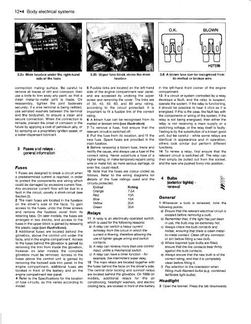
3.2a Main fusebox under the right-hand 3.2b Upper fuse block above the main 3.6 A blown fuse can be recognised from<br />
side of the facia fusebox ' its melted or broken wire<br />
connection mating surface. Be careful to<br />
remove all traces of dirt and corrosion, then<br />
use a knife to trim away any paint, so that a<br />
clean metal-to-metal joint is made. On<br />
reassembly, tighten the joint fasteners<br />
securely; if a wire terminal is being refitted,<br />
use serrated washers between the terminal<br />
and the bodyshell, to ensure a clean and<br />
secure connection. When the connection is<br />
remade, prevent the onset of corrosion in the<br />
future by applying a coat of petroleum jelly, or<br />
by spraying on a proprietary ignition sealer, or<br />
a water-dispersant lubricant.<br />
3 Fuses and relays -<br />
general information<br />
Fuses<br />
1 Fuses are designed to break a circuit when<br />
a predetermined current is reached, in order<br />
to protect the components and wiring which<br />
could be damaged by excessive current flow.<br />
Any excessive current flow will be due to a<br />
fault in the circuit, usually a short-circuit (see<br />
Section 2).<br />
2 The main fuses are located in the fusebox<br />
on the driver's side of the facia. <strong>To</strong> gain<br />
access to the fuses, undo the three screws<br />
and remove the fusebox cover from its<br />
retaining tabs. On later models, the fuses are<br />
arranged in two blocks, and access to the<br />
fuses in the upper block is gained by releasing<br />
the plastic cage (see illustrations).<br />
3 Additional fuses are located behind the<br />
glovebox, above the control unit under the<br />
facia, and in the engine compartment. Access<br />
to the fuses behind the glovebox is gained by<br />
removing the trim from inside the glovebox,<br />
however on later models the complete<br />
glovebox must be removed. Access to the<br />
fuses above the control unit is gained by<br />
removing the footwell side trim panel. In the<br />
engine compartment, additional fuses are<br />
located in front of the battery and on the<br />
engine compartment rear panel.<br />
4 Refer to the Specifications for the location<br />
of fuse circuits, as this varies according to<br />
model.<br />
5 Fusible links are located on the left-hand<br />
side of the engine compartment rear panel,<br />
and are accessed by undoing the upper<br />
screw and removing the cover. The links are<br />
of 30, 40, 50, 60, and 80 amp rating,<br />
according to the circuit protected. It is<br />
important to fit a fusible link of the correct<br />
rating.<br />
6 A blown fuse can be recognised from its<br />
melted or broken wire (see illustration).<br />
7 <strong>To</strong> remove a fuse, first ensure that the<br />
relevant circuit is switched off.<br />
8 Pull the fuse from its location, and fit the<br />
new fuse. Spare fuses are provided in the<br />
main fusebox.<br />
9 Before renewing a blown fuse, trace and<br />
rectify the cause, and always use a fuse of the<br />
correct rating. Never substitute a fuse of a<br />
higher rating, or make temporary repairs using<br />
wire or metal foil, as more serious damage, or<br />
even fire, could result.<br />
10 Note that the fuses are colour-coded as<br />
follows. Refer to the wiring diagrams for<br />
details of the fuse ratings used and the<br />
circuits protected.<br />
Colour Rating<br />
Orange 7.5A<br />
Red 10A<br />
Blue 15A<br />
Yellow 20A<br />
Green 30A<br />
Relays<br />
11 A relay is an electrically-operated switch,<br />
which is used for the following reasons:<br />
a) A relay can switch a heavy current<br />
remotely from the circuit in which the<br />
current is flowing, therefore allowing the<br />
use of lighter-gauge wiring and switch<br />
contacts.<br />
b) A relay can receive more than one control<br />
input, unlike a mechanical switch.<br />
c) A relay can have a timer function - for<br />
example, the intermittent wiper relay.<br />
12 The main relays are located together with<br />
the fuses behind the facia on the driver's side.<br />
The central door locking and sunroof relays<br />
are located behind the glovebox. On 1998-on<br />
models, additional relays for the air<br />
conditioning, headlight washers, and electric<br />
cooling fans, are located in front of the battery<br />
in the left-hand front corner of the engine<br />
compartment.<br />
13 If a circuit or system controlled by a relay<br />
develops a fault, and the relay is suspect,<br />
operate the system. If the relay is functioning,<br />
it should be possible to hear it click as it is<br />
energised. If this is the case, the fault lies with<br />
the components or wiring of the system. If the<br />
relay is not being energised, then either the<br />
relay is not receiving a main supply or a<br />
switching voltage, or the relay itself is faulty.<br />
Testing is by the substitution of a known good<br />
unit, but be careful - while some relays are<br />
identical in appearance and in operation,<br />
others look similar but perform different<br />
functions.<br />
14 <strong>To</strong> renew a relay, first ensure that the<br />
relevant circuit is switched off. The relay can<br />
then simply be pulled out from the socket,<br />
and the new one pushed firmly into position.<br />
4 Bulbs<br />
(exterior lights) - |g<br />
renewal<br />
General<br />
1 Whenever a bulb is renewed, note the<br />
following points:<br />
a) Ensure that the relevant electrical circuit is<br />
isolated before removing a bulb.<br />
b) Remember that, if the light has just been<br />
in use, the bulb may be extremely hot.<br />
c) Always check the bulb contacts and<br />
holder, ensuring that there is clean metalto-metal<br />
contact. Clean off any corrosion<br />
or dirt before fitting a new bulb.<br />
d) Where bayonet-type bulbs are fitted,<br />
ensure that the live contacts bear firmly<br />
against the bulb contacts.<br />
e) Always ensure that the new bulb is of the<br />
correct rating, and that it is completely<br />
clean before fitting it.<br />
f) Pay attention to the orientation when<br />
fitting multi-filament bulbs (e.g. combined<br />
tail/brake light bulbs).<br />
Headlight<br />
2 Open the bonnet. Press the tab downwards


