

Bravo & Brava • 1995 To 2000
Bravo & Brava • 1995 To 2000
Bravo & Brava • 1995 To 2000

You also want an ePaper? Increase the reach of your titles
YUMPU automatically turns print PDFs into web optimized ePapers that Google loves.
Body electrical systems 12»15<br />
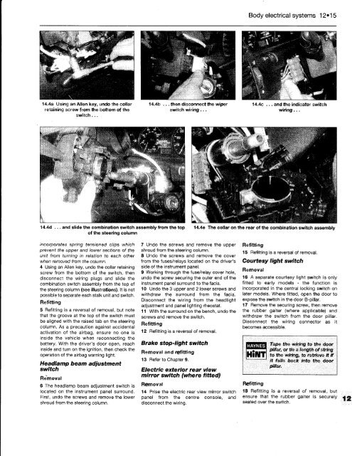
14.4a Using an Allen key, undo the collar 14.4b ... then disconnect the wiper 14.4c ... and the indicator switch<br />
retaining screw from the bottom of the switch wiring ... wiring ...<br />
switch ...<br />
incorporates spring tensioned clips which<br />
prevent the upper and lower sections of the<br />
unit from turning in relation to each other<br />
when removed from the column.<br />
4 Using an Allen key, undo the collar retaining<br />
screw from the bottom of the switch, then<br />
disconnect the wiring plugs and slide the<br />
combination switch assembly from the top of<br />
the steering column (see illustrations). It is not<br />
possible to separate each stalk unit and switch.<br />
Refitting<br />
5 Refitting is a reversal of removal, but note<br />
that the groove at the top of the switch must<br />
be aligned with the raised tab on the steering<br />
column. As a precaution against accidental<br />
activation of the airbag, ensure no one is<br />
inside the vehicle when reconnecting the<br />
battery. With the driver's door open, reach<br />
inside and turn on the ignition, then check the<br />
operation of the airbag warning light.<br />
Headlamp beam adjustment<br />
switch<br />
Removal<br />
6 The headlamp beam adjustment switch is<br />
located on the instrument panel surround.<br />
First, undo the screws and remove the lower<br />
shroud from the steering column.<br />
7 Undo the screws and remove the upper<br />
shroud from the steering column.<br />
8 Undo the screws and remove the cover<br />
from the fuses/relays located on the driver's<br />
side of the instrument panel.<br />
9 Working through the fuse/relay cover hole,<br />
undo the screw securing the outer end of the<br />
instrument panel surround to the facia.<br />
10 Undo the 3 upper and 2 lower screws and<br />
withdraw the surround from the facia.<br />
Disconnect the wiring from the headlight<br />
adjustment and panel lighting rheostat.<br />
11 With the surround on the bench, undo the<br />
screws and remove the switch.<br />
Refitting<br />
12 Refitting is a reversal of removal.<br />
Brake stop-light switch<br />
Removal and refitting<br />
13 Refer to Chapter 9.<br />
Electric exterior rear view<br />
mirror switch (where fitted)<br />
Removal<br />
14 Prise the electric rear view mirror switch<br />
panel from the centre console, and<br />
disconnect the wiring.<br />
Refitting<br />
15 Refitting is a reversal of removal.<br />
Courtesy light switch<br />
Removal<br />
16 A separate courtesy light switch is only<br />
fitted to early models - the function is<br />
incorporated in the central locking switch on<br />
later models. Where fitted, open the door to<br />
expose the switch in the door B-pillar.<br />
17 Remove the securing screw, then remove<br />
the rubber gaiter (where applicable) and<br />
withdraw the switch from the door pillar.<br />
Disconnect the wiring connector as it<br />
becomes accessible.<br />
HAYNES<br />
Refitting<br />
Tape the wiring to the door<br />
pillar, or tie a length of string<br />
to the wiring, to retrieve It If<br />
it falls back into the door<br />
pillar.<br />
18 Refitting is a reversal of removal, but<br />
ensure that the rubber gaiter is securely<br />
seated over the switch.


