

Bravo & Brava • 1995 To 2000
Bravo & Brava • 1995 To 2000
Bravo & Brava • 1995 To 2000

Create successful ePaper yourself
Turn your PDF publications into a flip-book with our unique Google optimized e-Paper software.
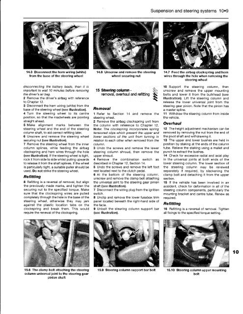
14.3 Disconnect the horn wiring (white)<br />
from the base of the steering wheel<br />
disconnecting the battery leads, then it is<br />
important to wait 10 minutes before removing<br />
the driver's air bag.<br />
2 Remove the driver's airbag with reference<br />
to Chapter 12.<br />
3 Disconnect the horn wiring (white) from the<br />
base of the steering wheel (see illustration).<br />
4 Turn the steering wheel to its centre<br />
position, so that the roadwheels are pointing<br />
straight ahead.<br />
5 Make alignment marks between the<br />
steering wheel and the end of the steering<br />
column shaft, to aid correct refitting later.<br />
6 Unscrew and remove the steering wheel<br />
securing nut (see illustration).<br />
7 Remove the steering wheel from the inner<br />
column splines, while feeding the airbag<br />
clockspring and horn wires through the hole<br />
(see illustration). If the steering wheel is tight,<br />
rock it from side to side whilst pulling upwards<br />
to release it from the shaft splines. If the wheel<br />
is particularly tight, a suitable puller should be<br />
used. Do not strike the steering wheel.<br />
Refitting<br />
8 Refitting is a reversal of removal, but align<br />
the previously made marks, and tighten the<br />
securing nut to the specified torque. Make<br />
sure that the clockspring wires are pulled<br />
completely through the hole in the base of the<br />
steering wheel, otherwise they may jam<br />
against the plastic location tabs on the<br />
clockspring and break them. This would<br />
require the renewal of the clockspring.<br />
15.6 The clamp bolt attaching the steering<br />
column universal joint to the steering gear<br />
pinion shaft<br />
14.6 Unscrew and remove the steering<br />
wheel securing nut<br />
15 Steering column - ^<br />
removal, overhaul and refitting<br />
Removal<br />
1 Refer to Section 14 and remove the<br />
steering wheel.<br />
2 Remove the airbag clockspring unit from<br />
the column with reference to Chapter 12.<br />
Note: The clockspring incorporates spring<br />
tensioned clips which prevent the upper and<br />
lower sections of the unit from turning in<br />
relation to each other when removed from the<br />
column.<br />
3 Undo the screws and remove the lower<br />
steering column shroud, then remove the<br />
upper shroud.<br />
4 Remove the combination switch as<br />
described in Chapter 12, Section 14.<br />
5 Undo the screws and remove the left foot<br />
rest located next to the clutch pedal.<br />
6 At the bottom of the steering column,<br />
unscrew and remove the clamp bolt attaching<br />
the universal joint to the steering gear pinion<br />
shaft (see illustration).<br />
7 Disconnect the wiring plug from the ignition<br />
switch.<br />
8 Unclip and remove the lower fusebox trim<br />
panel located beneath the right-hand side of<br />
the facia.<br />
9 Unbolt the steering column support bar<br />
(see illustration).<br />
15.9 Steering column support bar bolt<br />
Suspension and steering systems 10*9<br />
14.7 Feed the airbag clockspring and horn<br />
wires through the hole when removing the<br />
steering wheel<br />
10 Support the steering column, then<br />
unscrew and remove the upper mounting<br />
bolts and lower it from the bulkhead (see<br />
illustration). Lift the steering column and<br />
release the lower universal joint from the<br />
steering gear pinion. Note that the pinion has<br />
a master spline.<br />
11 Withdraw the steering column from inside<br />
the vehicle.<br />
Overhaul<br />
12 The height adjustment mechanism can be<br />
removed by removing the nut from the end of<br />
the pivot shaft and withdrawing it.<br />
13 The upper and lower bushes are held in<br />
position by staking at the ends of the column<br />
tube. Relieve the staking using a mallet and<br />
punch to extract the bushes.<br />
14 Check for excessive radial and axial play<br />
in the universal joints at both ends of the<br />
lower steering column. The lower section of<br />
the steering column may be renewed<br />
separately if required, by slackening the<br />
clamp bolt and detaching it from the upper<br />
section.<br />
15 If the vehicle has been involved in an<br />
accident, check for deformation in all of the<br />
steering column components, particularly the<br />
mounting bracket and centre tube. Renew as<br />
required.<br />
Refitting<br />
16 Refitting is a reversal of removal. Tighten<br />
all fixings to the specified torque setting.<br />
15.10 Steering column upper mounting<br />
bolt


