

Bravo & Brava • 1995 To 2000
Bravo & Brava • 1995 To 2000
Bravo & Brava • 1995 To 2000

You also want an ePaper? Increase the reach of your titles
YUMPU automatically turns print PDFs into web optimized ePapers that Google loves.
8*4 Driveshafts<br />
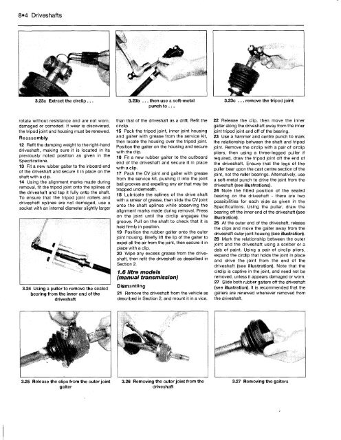
3.23a Extract the circlip ...<br />
rotate without resistance and are not worn,<br />
damaged or corroded. If wear is discovered,<br />
the tripod joint and housing must be renewed.<br />
Reassembly<br />
12 Refit the damping weight to the right-hand<br />
driveshaft, making sure it is located in its<br />
previously noted position as given in the<br />
Specifications.<br />
13 Fit a new rubber gaiter to the inboard end<br />
of the driveshaft and secure it in place on the<br />
shaft with a clip.<br />
14 Using the alignment marks made during<br />
removal, fit the tripod joint onto the splines of<br />
the driveshaft and tap it fully onto the shaft.<br />
<strong>To</strong> ensure that the tripod joint rollers and<br />
driveshaft splines are not damaged, use a<br />
socket with an internal diameter slightly larger<br />
3.24 Using a puller to remove the sealed<br />
bearing from the inner end of the<br />
driveshaft<br />
3.25 Release the clips from the outer joint<br />
gaiter<br />
3.23b ... then use a soft-metal<br />
punch to ...<br />
than that of the driveshaft as a drift. Refit the<br />
circlip.<br />
15 Pack the tripod joint, inner joint housing<br />
and gaiter with grease from the service kit,<br />
then locate the housing over the tripod joint.<br />
Position the gaiter on the housing and secure<br />
with the clip.<br />
16 Fit a new rubber gaiter to the outboard<br />
end of the driveshaft and secure it in place<br />
with a clip.<br />
17 Pack the CV joint and gaiter with grease<br />
from the service kit, pushing it into the joint<br />
ball grooves and expelling any air that may be<br />
trapped underneath.<br />
18 Lubricate the splines of the drive shaft<br />
with a smear of grease, then slide the CV joint<br />
onto the shaft splines while observing the<br />
alignment marks made during removal. Press<br />
on the joint until the circlip engages the<br />
groove. Pull on the shaft to check that it is<br />
held firmly in position.<br />
19 Position the rubber gaiter onto the outer<br />
joint housing. Briefly lift the lip of the gaiter to<br />
expel all the air from the joint, then secure it in<br />
place with a clip.<br />
20 Wipe any excess grease from the driveshaft,<br />
then refit the driveshaft as described in<br />
Section 2.<br />
1.6 litre models<br />
(manual transmission)<br />
Dismantling<br />
21 Remove the driveshaft from the vehicle as<br />
described in Section 2, and mount it in a vice.<br />
3.26 Removing the outer joint from the<br />
driveshaft<br />
3.23c ... remove the tripod joint<br />
22 Release the clip, then move the inner<br />
gaiter along the driveshaft away from the inner<br />
joint tripod joint and off of the bearing.<br />
23 Use a hammer and centre punch to mark<br />
the relationship between the shaft and tripod<br />
joint. Remove the circlip with a pair of circlip<br />
pliers, then using a three-legged puller if<br />
required, draw the tripod joint off the end of<br />
the driveshaft. Ensure that the legs of the<br />
puller bear upon the cast centre section of the<br />
joint, not the roller bearings. Alternatively, use<br />
a soft-metal punch to drive the joint from the<br />
driveshaft (see illustrations).<br />
24 Note the fitted position of the sealed<br />
bearing on the driveshaft - there are two<br />
possibilities for each side as given in the<br />
Specifications. Using the puller, draw the<br />
bearing off the inner end of the driveshaft (see<br />
illustration).<br />
25 At the outer end of the driveshaft, release<br />
the clips and move the gaiter away from the<br />
driveshaft outer joint housing (see illustration).<br />
26 Mark the relationship between the outer<br />
joint and the driveshaft using a scriber or a<br />
dab of paint. Using a pair of circlip pliers,<br />
expand the circlip that holds the joint in place<br />
and drive the joint from the end of the<br />
driveshaft (see illustration). Note that the<br />
circlip is captive in the joint, and need not be<br />
removed, unless it appears damaged or worn.<br />
27 Slide both rubber gaiters off the driveshaft<br />
(see illustration). It is recommended that the<br />
gaiters are renewed whenever removed from<br />
the driveshaft.<br />
3.27 Removing the gaiters


