

Bravo & Brava • 1995 To 2000
Bravo & Brava • 1995 To 2000
Bravo & Brava • 1995 To 2000

Create successful ePaper yourself
Turn your PDF publications into a flip-book with our unique Google optimized e-Paper software.
Refitting<br />
17 Refitting is a reversal of removal, ensuring<br />
that the diaphragm and cover are fitted the<br />
correct way round, and that the retaining<br />
screws are securely tightened.<br />
Idle control stepper motor<br />
Removal<br />
18 Remove the air box and the associated air<br />
ducting from the top of the throttle body as<br />
described in Section 2.<br />
19 Using a crosshead screwdriver, unscrew<br />
the three mounting screws and remove the<br />
stepper motor from the throttle body. Recover<br />
the gasket.<br />
20 Clean the unit and check for damage and<br />
wear.<br />
Refitting<br />
21 When refitting the unit, use a new gasket<br />
and make sure that the plunger is inserted<br />
correctly using the following procedure:<br />
a) Insert the unit and refit the mounting<br />
screws loosely.<br />
b) Reconnect the wiring, then switch on the<br />
ignition several times so that the unit<br />
centralises itself.<br />
c) Securely tighten the mounting screws.<br />
d) Disconnect the battery negative cable,<br />
and leave it disconnected for about<br />
20 minutes - the injection/ignition ECU<br />
will then position the idle control stepper<br />
motor correctly when the battery is<br />
reconnected and the engine is started for<br />
the first time.<br />
Throttle potentiometer<br />
22 The position of the throttle potentiometer<br />
with respect to the throttle disc is pre-set at<br />
the factory. Consequently, if the potentiometer<br />
is found to be faulty, the entire<br />
throttle body must be renewed.<br />
Inlet air temperature sensor<br />
23 The inlet air temperature sensor is an<br />
integral part of the fuel injector assembly, and<br />
cannot apparently be renewed separately -<br />
check with a FIAT dealer or Bosch agent.<br />
Coolant temperature sensor<br />
Removal<br />
24 The coolant temperature sensor is located<br />
5.38a Remove the screw at the front...<br />
5.26 Disconnect the wiring from the<br />
coolant temperature sensor<br />
on the left-hand side of the cylinder head,<br />
threaded into the coolant outlet elbow.<br />
25 Drain the cooling system with reference to<br />
Chapter 1.<br />
26 Unplug the wiring from the sensor at the<br />
connector (see illustration).<br />
27 Unscrew the sensor and remove it from<br />
the cylinder head. Recover the sealing washer<br />
where fitted. If using a socket, take care not to<br />
damage the wiring connector on the sensor.<br />
Refitting<br />
28 Refitting is a reversal of removal. Where<br />
applicable, fit a new sealing washer. Tighten<br />
the sensor to the specified torque. Do not<br />
exceed the specified torque otherwise the<br />
unit's threads may be damaged.<br />
Crankshaft TDC sensor<br />
29 Refer to Chapter 5B, Section 6.<br />
Electronic control unit (ECU)<br />
Note: The ECU communicates with the antitheft/immobiliser<br />
system when the vehicle is<br />
started; once the ignition key electronic code<br />
has been stored by the ECU, it cannot be<br />
used on any other vehicle. For this reason, do<br />
not attempt to diagnose problems with the<br />
engine management system by connecting<br />
the ECU to another vehicle, or by substituting<br />
an ECU from another vehicle.<br />
Removal<br />
30 The ECU (electronic control unit) is<br />
mounted on the bulkhead at the rear of the<br />
engine compartment.<br />
31 Prior to removal, disconnect the battery<br />
negative cable from its terminal. Discon-<br />
5.38b ... and at the rear...<br />
Fuel system - single-point injection 4A»7<br />
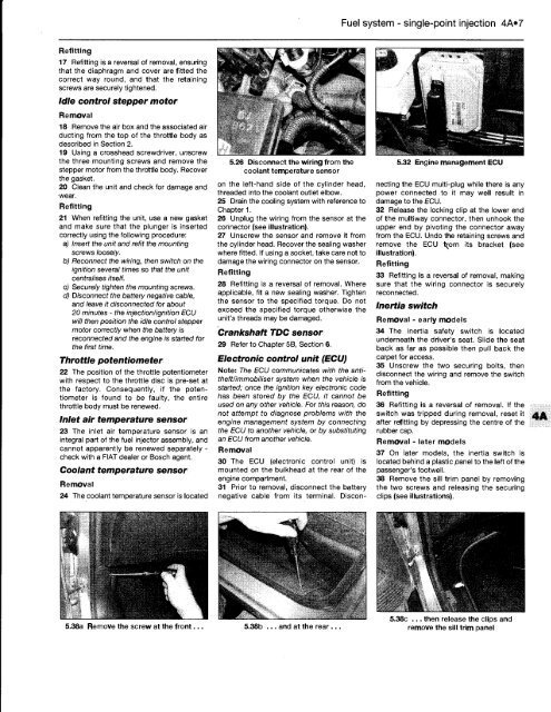
5.32 Engine management ECU<br />
necting the ECU multi-plug while there is any<br />
power connected to it may well result in<br />
damage to the ECU.<br />
32 Release the locking clip at the lower end<br />
of the multiway connector, then unhook the<br />
upper end by pivoting the connector away<br />
from the ECU. Undo the retaining screws and<br />
remove the ECU trom its bracket (see<br />
illustration).<br />
Refitting<br />
33 Refitting is a reversal of removal, making<br />
sure that the wiring connector is securely<br />
reconnected.<br />
Inertia switch<br />
Removal - early models<br />
34 The inertia safety switch is located<br />
underneath the driver's seat. Slide the seat<br />
back as far as possible then pull back the<br />
carpet for access.<br />
35 Unscrew the two securing bolts, then<br />
disconnect the wiring and remove the switch<br />
from the vehicle.<br />
Refitting<br />
36 Refitting is a reversal of removal. If the<br />
switch was tripped during removal, reset it<br />
after refitting by depressing the centre of the<br />
rubber cap.<br />
Removal - later models<br />
37 On later models, the inertia switch is<br />
located behind a plastic panel to the left of the<br />
passenger's footwell.<br />
38 Remove the sill trim panel by removing<br />
the two screws and releasing the securing<br />
clips (see illustrations).<br />
5.38c ... then release the clips and<br />
remove the sill trim panel


