

Bravo & Brava • 1995 To 2000
Bravo & Brava • 1995 To 2000
Bravo & Brava • 1995 To 2000

You also want an ePaper? Increase the reach of your titles
YUMPU automatically turns print PDFs into web optimized ePapers that Google loves.
9*10 Braking system<br />
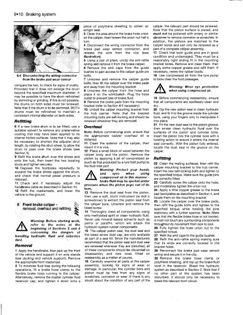
8.4 Disconnecting the wiring connector<br />
from the brake pad wear sensor<br />
compare the two, to check for signs of ovality.<br />
Provided that it does not enlarge the drum<br />
beyond the specified maximum diameter, it<br />
may be possible to have the drum refinished<br />
by skimming or grinding. If this is not possible,<br />
the drums on both sides must be renewed.<br />
Note that if the drum is to be skimmed, BOTH<br />
drums must be refinished to maintain a<br />
consistent internal diameter on both sides.<br />
Refitting<br />
8 If a new brake drum is to be fitted, use a<br />
suitable solvent to remove any preservative<br />
coating that may have been applied to its<br />
internal friction surfaces. Note that it may also<br />
be necessary to shorten the adjuster strut<br />
length, by rotating the strut wheel, to allow the<br />
drum to pass over the brake shoes (see<br />
Section 5).<br />
9 Refit the brake drum over the shoes and<br />
onto the hub, then insert the two locating<br />
studs and tighten securely.<br />
10 Depress the footbrake repeatedly to<br />
expand the brake shoes against the drum,<br />
and check that normal pedal pressure is<br />
restored.<br />
11 Check and if necessary adjust the<br />
handbrake cable as described in Section 14.<br />
12 Refit the roadwheels, and lower the<br />
vehicle to the ground.<br />
8 Front brake caliper -<br />
removal, overhaul and refitting ^<br />
A<br />
Warning: Before starting work,<br />
refer to the notes at the<br />
beginning of Sections 2 and 4<br />
concerning the dangers of<br />
handling<br />
dust.<br />
hydraulic fluid and asbestos<br />
Removal<br />
1 Apply the handbrake, then jack up the front<br />
of the vehicle and support it on axle stands<br />
(see Jacking and vehicle support). Remove<br />
the appropriate front roadwheel.<br />
2 <strong>To</strong> minimise fluid loss during the following<br />
operations, fit a brake hose clamp to the<br />
flexible brake hose running to the caliper.<br />
Alternatively, remove the master cylinder fluid<br />
reservoir cap, and tighten it down onto a<br />
piece of polythene sheeting to obtain an<br />
airtight seal.<br />
3 Clean the area around the brake hose union<br />
on the caliper, then loosen the union nut half a<br />
turn.<br />
4 Disconnect the wiring connector from the<br />
brake pad wear sensor connector, and<br />
release the wire from the clip (see<br />
illustration).<br />
5 Using a pair of pliers, unclip the anti-rattle<br />
spring and remove it from the brake caliper.<br />
6 Remove the end caps from the guide<br />
bushes to gain access to the caliper guide pin<br />
bolts.<br />
7 Unscrew and remove the caliper guide<br />
bolts, then lift the caliper over the brake pads<br />
and away from the mounting bracket.<br />
8 Unscrew the caliper from the hose and<br />
place it on the workbench. Plug the hose<br />
outlet to prevent loss of brake fluid.<br />
9 Remove the brake pads from the mounting<br />
bracket (refer to Section 4 if necessary).<br />
10 Unbolt the caliper mounting bracket from<br />
the hub carrier. Note that the bracket<br />
mounting bolts are self-locking and should be<br />
renewed whenever they are removed.<br />
Overhaul<br />
Note: Before commencing work, ensure that<br />
the appropriate caliper overhaul kit is<br />
obtained.<br />
11 Clean the exterior of the caliper, then<br />
mount it in a vice.<br />
12 Place a small block of wood between the<br />
caliper body and the piston. Remove the<br />
piston by applying a jet of compressed air<br />
(such as that produced by a tyre foot pump) to<br />
the fluid inlet port.<br />
A<br />
Warning: Protect your hands<br />
and eyes when using<br />
compressed air in this manner -<br />
brake fluid may be ejected under<br />
pressure when the piston pops out of its<br />
bore.<br />
13 Remove the dust seal from the piston,<br />
then use a soft, blunt instrument (ie not a<br />
screwdriver) to extract the piston seal from<br />
the caliper bore. Unscrew and remove the<br />
bleed screw.<br />
14 Thoroughly clean all components, using<br />
only methylated spirit or clean hydraulic fluid.<br />
Never use mineral-based solvents such as<br />
petrol or paraffin, which will attack the<br />
hydraulic system rubber components.<br />
15 The caliper piston seal, the dust seal and<br />
the bleed screw dust cap, are only available<br />
as part of a seal kit. Since the manufacturers<br />
recommend that the piston seal and dust seal<br />
are renewed whenever they are disturbed, all<br />
of these components should be discarded on<br />
disassembly and new ones fitted on<br />
reassembly as a matter of course.<br />
16 Carefully examine all parts of the caliper<br />
assembly, looking for signs of wear or<br />
damage. In particular, the cylinder bore and<br />
piston must be free from any signs of<br />
scratches, corrosion or wear. If there is any<br />
doubt about the condition of any part of the<br />
caliper, the relevant part should be renewed.<br />
Note that the piston surface is plated, and<br />
must not be polished with emery or similar<br />
abrasives to remove corrosion or scratches. In<br />
addition, the pistons are matched to the<br />
caliper bores and can only be renewed as a<br />
part of a complete caliper assembly.<br />
17 Check that both guide pins are in good<br />
condition and undamaged. They must be a<br />
reasonably tight sliding fit in the mounting<br />
bracket bores. Remove and clean them, then<br />
apply some copper grease and refit them. If<br />
necessary, renew the rubber boots.<br />
18 Use compressed air from the tyre pump<br />
to blow clear the fluid passages.<br />
A Warning: Wear eye protection<br />
when using compressed air.<br />
19 Before commencing reassembly, ensure<br />
that all components are spotlessly-clean and<br />
dry.<br />
20 Dip the new piston seal in clean hydraulic<br />
fluid, and fit it to the groove inside the cylinder<br />
bore, using your fingers only to manipulate it<br />
into place.<br />
21 Fit the new dust seal to the piston groove,<br />
then smear clean hydraulic fluid over the<br />
surfaces of the piston and cylinder bore.<br />
Insert the piston into the cylinder bore with a<br />
twisting action to ensure it enters the internal<br />
seal correctly. With the piston fully entered,<br />
locate the dust seal in the groove on the<br />
caliper.<br />
Refitting<br />
22 Clean the mating surfaces, then refit the<br />
caliper mounting bracket to the hub carrier.<br />
Insert the new self-locking bolts and tighten to<br />
the specified torque. Make sure the guide pins<br />
are correctly fitted<br />
23 Carefully screw the caliper onto the hose,<br />
and moderately tighten the union nut.<br />
24 Apply a little copper grease to the brake<br />
pad backplates as described in Section 4, and<br />
locate them on the mounting bracket<br />
25 Locate the caliper over the brake pads,<br />
then refit the guide bolts and tighten to the<br />
specified torque while holding the pins<br />
stationary with a further spanner. Note: Make<br />
sure that the flexible brake hose is not twisted.<br />
It must not touch any surrounding components<br />
throughout its movement from lock to lock.<br />
26 Fully tighten the hose union nut to the<br />
specified torque.<br />
27 Refit the end caps to the guide bushes.<br />
28 Refit the anti-rattle spring making sure<br />
that its ends are correctly located in the<br />
bracket holes.<br />
29 Reconnect the brake pad wear sensor<br />
wiring and secure it in the clip.<br />
30 Remove the brake hose clamp or<br />
polythene sheeting, and top up the brake fluid<br />
level in the reservoir. Bleed the hydraulic<br />
system as described in Section 2. Note that if<br />
no other part of the system has been<br />
disturbed, it should only be necessary to<br />
bleed the relevant front circuit.


