

Bravo & Brava • 1995 To 2000
Bravo & Brava • 1995 To 2000
Bravo & Brava • 1995 To 2000

You also want an ePaper? Increase the reach of your titles
YUMPU automatically turns print PDFs into web optimized ePapers that Google loves.
9*16 Braking system<br />
2 Unbolt the exhaust rear and intermediate<br />
mountings from the underbody.<br />
3 Unbolt the heat shield for access to the rear<br />
brake pressure proportioning valve.<br />
4 Unscrew the cap from the brake fluid<br />
reservoir and tighten it down onto a piece of<br />
polythene sheeting. This will help reduce the<br />
loss of fluid from the system. Also place a<br />
container beneath the valve to catch spilt fluid.<br />
5 Identify the pipe locations on the valve,<br />
then unscrew the union nuts and disconnect<br />
them. If possible, plug the ends of the pipes to<br />
prevent loss of fluid.<br />
6 Disconnect the spring from the lever on top<br />
of the valve.<br />
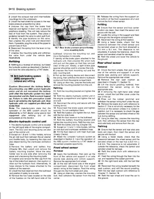
7 Unscrew the mounting bolts and withdraw<br />
the valve from under the vehicle (see<br />
illustration).<br />
Refitting<br />
8 Refitting is a reversal of removal, but bleed<br />
the hydraulic system as described in Section 2,<br />
and have the valve adjusted by a FIAT dealer.<br />
19 Anti-lock braking system<br />
(ABS) components -<br />
removal and refitting<br />
Caution: Disconnect the battery before<br />
disconnecting any ABS system hydraulic<br />
union and do not reconnect the battery<br />
until after the hydraulic system has been<br />
reconnected and the fluid reservoir topped<br />
up. Failure to take this precaution could<br />
lead to air entering the hydraulic unit. New<br />
hydraulic units are supplied pre-filled with<br />
brake fluid.<br />
Note: The manufacturers state that the<br />
operation of the ABS system should be<br />
checked by a FIAT dealer using special test<br />
equipment after refitting any of the<br />
components in this Section.<br />
Electro-hydraulic control unit<br />
1 The electro-hydraulic control unit is located<br />
on the left-hand side of the engine compartment.<br />
The ECU and recycling pump are also<br />
part of the control unit.<br />
2 Except on 1.3 and 1.4 litre models, remove<br />
the air inlet duct from between the air cleaner<br />
and throttle body, by loosening the clips and<br />
also disconnecting the crankcase ventilation<br />
hose.<br />
3 Remove the battery and battery tray<br />
(Chapter 5A), then unbolt and remove the<br />
battery mounting bracket. Move the relay<br />
holder box to one side after removing the<br />
cover and unscrewing the mounting bolts.<br />
4 Unscrew and remove the filler cap from the<br />
top of the brake fluid reservoir, then syphon or<br />
draw out the hydraulic fluid. Alternatively, fit<br />
hose clamps to the hoses attached to the<br />
bottom of the reservoir.<br />
5 Unbolt the fluid reservoir from the bulkhead<br />
and position it safely to one side.<br />
6 Remove the two fuses located on the side<br />
of the fusebox on the left-hand side of the<br />
L_ J* . 1<br />
18.7 Rear brake pressure proportioning<br />
valve mounting bolts<br />
bulkhead. Unscrew the mounting nut, and<br />
move the fusebox to one side.<br />
7 Identify all the brake pipes attached to the<br />
hydraulic unit, then unscrew the union nuts<br />
and pull out the pipes so that they are just<br />
clear of the unit. Ideally, a split brake pipe<br />
spanner should be used to unscrew the nuts.<br />
8 Unscrew the front mounting nut and the<br />
side mounting bolt.<br />
9 Pull up the locking device and disconnect<br />
the wiring, then withdraw the electro-hydraulic<br />
control unit from the engine compartment.<br />
10 Using an Allen key, unscrew the bolts and<br />
remove the mounting bracket from the unit.<br />
Refitting<br />
11 Refit the mounting bracket and tighten the<br />
bolts.<br />
12 Refit the electro-hydraulic control unit in<br />
the engine compartment and tighten the nut<br />
and bolt.<br />
13 Reconnect the wiring and secure with the<br />
locking device.<br />
14 Reconnect the brake pipes and tighten<br />
securely. Do not overtighten them.<br />
15 Refit the fusebox and tighten the nut, then<br />
refit the two side fuses.<br />
16 Refit the fluid reservoir to the bulkhead.<br />
17 Refit the battery mounting bracket and<br />
tighten the mounting bolts. Refit the relay box.<br />
18 Refit the battery and tray (Chapter 5A).<br />
19 Except on 1.3 and 1.4 litre models, refit the<br />
air inlet duct and crankcase ventilation hose.<br />
20 Fill the fluid reservoir with fresh fluid (see<br />
Weekly Checks).<br />
21 Bleed the complete hydraulic system as<br />
described in Section 2. Have the operation of<br />
the ABS system checked by a FIAT dealer at<br />
the earliest possible opportunity.<br />
Front wheel sensor<br />
Removal<br />
22 Apply the handbrake, then jack up the<br />
front of the vehicle and support it on axle<br />
stands (see Jacking and vehicle support).<br />
Remove the appropriate front wheel.<br />
23 At the rear left-hand side of the engine<br />
compartment, disconnect the front wheel<br />
sensor wiring at the fusebox. Feed the wiring<br />
through into the front wheel arch area.<br />
24 Using an Allen key, unscrew the mounting<br />
bolt, then withdraw the sensor from the hub<br />
carrier.<br />
25 Release the wiring from the support on<br />
the bottom of the front suspension strut and<br />
remove the front wheel sensor.<br />
Refitting<br />
26 Ensure that the sensor and hub carrier<br />
location are clean, then insert the sensor and<br />
secure with the bolt.<br />
27 Locate the wiring in the support and feed<br />
it through into the engine compartment.<br />
28 Reconnect the wiring at the fusebox.<br />
29 Using a feeler blade, check that the<br />
clearance between the wheel sensor and<br />
the serrated wheel on the front driveshaft is<br />
0.9 mm ± 0.4 mm. The clearance is not<br />
adjustable; if outside the tolerance, check the<br />
sensor and serrated wheel for damage.<br />
30 Refit the wheel and lower the vehicle to<br />
the ground.<br />
Rear wheel sensor<br />
Removal<br />
31 Chock the front wheels, then jack up the<br />
rear of the vehicle and support it on axie<br />
stands (see Jacking and vehicle support).<br />
Remove the appropriate rear wheel.<br />
32 Remove the rear seat cushion as<br />
described in Chapter 11, Section 19.<br />
33 Lift the sound proofing material, then<br />
disconnect the sensor wiring on the<br />
appropriate side.<br />
34 If removing the right-hand side wheel<br />
sensor, unbolt the fuel filter cover under the<br />
rear of the car.<br />
35 Prise out the rubber grommet and<br />
withdraw the sensor wiring from under the car.<br />
36 Remove the brake drum with reference to<br />
Section 7. This is not strictly necessary for the<br />
removal of the sensor unless it is rusted in<br />
position, but it is necessary to check the gap<br />
between the sensor and serrated wheel on the<br />
hub during refitting.<br />
37 Using an Allen key, unscrew the mounting<br />
bolt, then withdraw the sensor from the rear<br />
stub axle body and remove from the car.<br />
Refitting<br />
38 Ensure that the sensor and rear stub axle<br />
body are clean, then insert the sensor and<br />
secure with the bolt.<br />
39 Using a feeler blade, check that the<br />
clearance between the wheel sensor and the<br />
serrated wheel on the rear hub is 0.9 mm ±<br />
0.4" mm. The clearance is not adjustable; if<br />
outside the tolerance, check the sensor and<br />
serrated wheel for damage.<br />
40 Refit the brake drum with reference to<br />
Section 7.<br />
41 Feed the wiring through the floor into the<br />
car, and reposition the rubber grommet.<br />
42 On the right-hand side, refit the fuel filter<br />
cover.<br />
43 Reconnect the wiring located beneath the<br />
seat cushion, and refit the sound proofing.<br />
Refit the rear seat cushion with reference to<br />
Chapter 11, Section 19.<br />
44 Refit the rear wheel and lower the car to<br />
the ground.


