

Bravo & Brava • 1995 To 2000
Bravo & Brava • 1995 To 2000
Bravo & Brava • 1995 To 2000

Create successful ePaper yourself
Turn your PDF publications into a flip-book with our unique Google optimized e-Paper software.
204 1.6 litre engine in-car repair procedures<br />
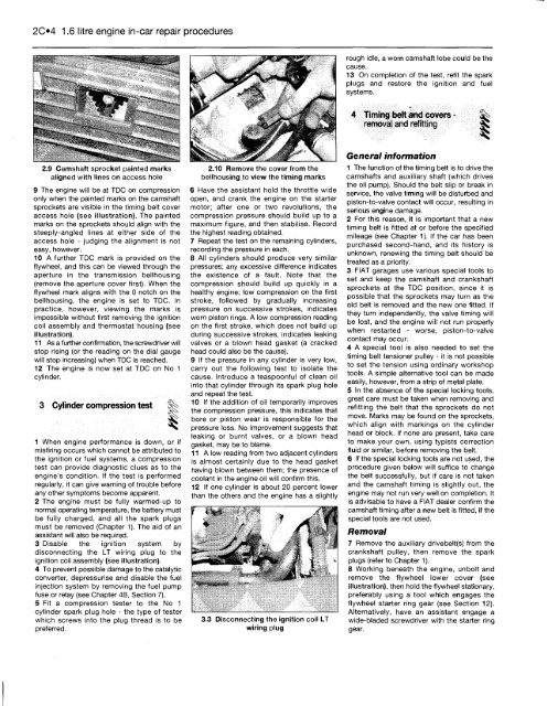
2.9 Camshaft sprocket painted marks<br />
aligned with lines on access hole<br />
9 The engine will be at TDC on compression<br />
only when the painted marks on the camshaft<br />
sprockets are visible in the timing belt cover<br />
access hole (see illustration). The painted<br />
marks on the sprockets should align with the<br />
steeply-angled lines at either side of the<br />
access hole - judging the alignment is not<br />
easy, however.<br />
10 A further TDC mark is provided on the<br />
flywheel, and this can be viewed through the<br />
aperture in the transmission bellhousing<br />
(remove the aperture cover first). When the<br />
flywheel mark aligns with the 0 notch on the<br />
bellhousing, the engine is set to TDC. In<br />
practice, however, viewing the marks is<br />
impossible without first removing the ignition<br />
coil assembly and thermostat housing (see<br />
illustration).<br />
11 As a further confirmation, the screwdriver will<br />
stop rising (or the reading on the dial gauge<br />
will stop increasing) when TDC is reached.<br />
12 The engine is now set at TDC on No 1<br />
cylinder.<br />
3 Cylinder compression test §t*><br />
1 When engine performance is down, or if<br />
misfiring occurs which cannot be attributed to<br />
the ignition or fuel systems, a compression<br />
test can provide diagnostic clues as to the<br />
engine's condition. If the test is performed<br />
regularly, it can give warning of trouble before<br />
any other symptoms become apparent.<br />
2 The engine must be fully warmed-up to<br />
normal operating temperature, the battery must<br />
be fully charged, and all the spark plugs<br />
must be removed (Chapter 1). The aid of an<br />
assistant will also be required.<br />
3 Disable the ignition system by<br />
disconnecting the LT wiring plug to the<br />
ignition coil assembly (see illustration).<br />
4 <strong>To</strong> prevent possible damage to the catalytic<br />
converter, depressurise and disable the fuel<br />
injection system by removing the fuel pump<br />
fuse or relay (see Chapter 4B, Section 7).<br />
5 Fit a compression tester to the No 1<br />
cylinder spark plug hole - the type of tester<br />
which screws into the plug thread is to be<br />
preferred.<br />
2.10 Remove the cover from the<br />
bellhousing to view the timing marks<br />
6 Have the assistant hold the throttle wide<br />
open, and crank the engine on the starter<br />
motor; after one or two revolutions, the<br />
compression pressure should build up to a<br />
maximum figure, and then stabilise. Record<br />
the highest reading obtained.<br />
7 Repeat the test on the remaining cylinders,<br />
recording the pressure in each.<br />
8 All cylinders should produce very similar<br />
pressures; any excessive difference indicates<br />
the existence of a fault. Note that the<br />
compression should build up quickly in a<br />
healthy engine; low compression on the first<br />
stroke, followed by gradually increasing<br />
pressure on successive strokes, indicates<br />
worn piston rings. A low compression reading<br />
on the first stroke, which does not build up<br />
during successive strokes, indicates leaking<br />
valves or a blown head gasket (a cracked<br />
head could also be the cause).<br />
9 If the pressure in any cylinder is very low,<br />
carry out the following test to isolate the<br />
cause. Introduce a teaspoonful of clean oil<br />
into that cylinder through its spark plug hole<br />
and repeat the test.<br />
10 If the addition of oil temporarily improves<br />
the compression pressure, this indicates that<br />
bore or piston wear is responsible for the<br />
pressure loss. No improvement suggests that<br />
leaking or burnt valves, or a blown head<br />
gasket, may be to blame.<br />
11 A low reading from two adjacent cylinders<br />
is almost certainly due to the head gasket<br />
having blown between them; the presence of<br />
coolant in the engine oil will confirm this.<br />
12 If one cylinder is about 20 percent lower<br />
than the others and the engine has a slightly<br />
3.3 Disconnecting the ignition coil LT<br />
wiring plug<br />
rough idle, a worn camshaft lobe could be the<br />
cause.<br />
13 On completion of the test, refit the spark<br />
plugs and restore the ignition and fuel<br />
systems.<br />
4 Timing belt and covers -<br />
removal and refitting ^<br />
General information<br />
1 The function of the timing belt is to drive the<br />
camshafts and auxiliary shaft (which drives<br />
the oil pump). Should the belt slip or break in<br />
service, the valve timing will be disturbed and<br />
piston-to-valve contact will occur, resulting in<br />
serious engine damage.<br />
2 For this reason, it is important that a new<br />
timing belt is fitted at or before the specified<br />
mileage (see Chapter 1). If the car has been<br />
purchased second-hand, and its history is<br />
unknown, renewing the timing belt should be<br />
treated as a priority.<br />
3 FIAT garages use various special tools to<br />
set and keep the camshaft and crankshaft<br />
sprockets at the TDC position, since it is<br />
possible that the sprockets may turn as the<br />
old belt is removed and the new one fitted. If<br />
they turn independently, the valve timing will<br />
be lost, and the engine will not run properly<br />
when restarted - worse, piston-to-valve<br />
contact may occur.<br />
4 A special tool is also needed to set the<br />
timing belt tensioner pulley - it is not possible<br />
to set the tension using ordinary workshop<br />
tools. A simple alternative tool can be made<br />
easily, however, from a strip of metal plate.<br />
5 In the absence of the special locking tools,<br />
great care must be taken when removing and<br />
refitting the belt that the sprockets do not<br />
move. Marks may be found on the sprockets,<br />
which align with markings on the cylinder<br />
head or block. If none are present, take care<br />
to make your own, using typists correction<br />
fluid or similar, before removing the belt.<br />
6 If the special locking tools are not used, the<br />
procedure given below will suffice to change<br />
the belt successfully, but if care is not taken<br />
and the camshaft timing is slightly out, the<br />
engine may not run very well on completion. It<br />
is advisable to have a FIAT dealer confirm the<br />
camshaft timing after a new belt is fitted, if the<br />
special tools are not used.<br />
Removal<br />
7 Remove the auxiliary drivebelt(s) from the<br />
crankshaft pulley, then remove the spark<br />
plugs (refer to Chapter 1).<br />
8 Working beneath the engine, unbolt and<br />
remove the flywheel lower cover (see<br />
illustration), then hold the flywheel stationary,<br />
preferably using a tool which engages the<br />
flywheel starter ring gear (see Section 12).<br />
Alternatively, have an assistant engage a<br />
wide-bladed screwdriver with the starter ring<br />
gear.


