

Bravo & Brava • 1995 To 2000
Bravo & Brava • 1995 To 2000
Bravo & Brava • 1995 To 2000

You also want an ePaper? Increase the reach of your titles
YUMPU automatically turns print PDFs into web optimized ePapers that Google loves.
10*6 Suspension and steering systems<br />
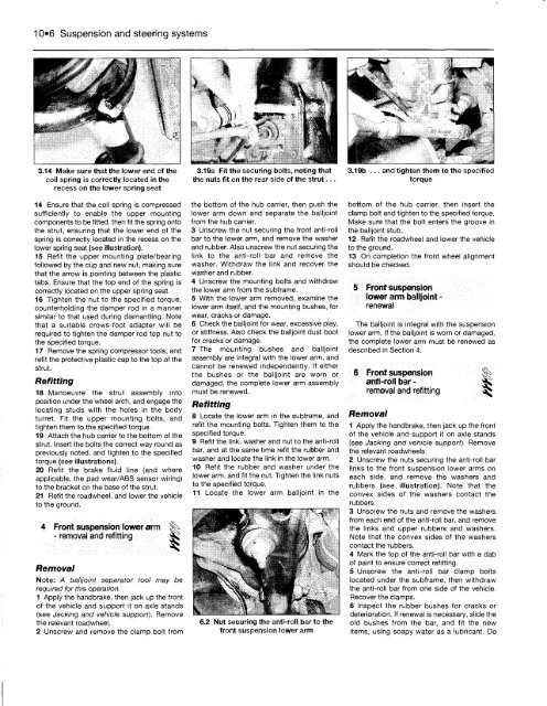
3.14 Make sure that the lower end of the<br />
coil spring is correctly located in the<br />
recess on the lower spring seat<br />
14 Ensure that the coil spring is compressed<br />
sufficiently to enable the upper mounting<br />
components to be fitted, then fit the spring onto<br />
the strut, ensuring that the lower end of the<br />
spring is correctly located in the recess on the<br />
lower spring seat (see illustration).<br />
15 Refit the upper mounting plate/bearing<br />
followed by the cup and new nut, making sure<br />
that the arrow is pointing between the plastic<br />
tabs. Ensure that the top end of the spring is<br />
correctly located on the upper spring seat.<br />
16 Tighten the nut to the specified torque,<br />
counterholding the damper rod in a manner<br />
similar to that used during dismantling. Note<br />
that a suitable crows-foot adapter will be<br />
required to tighten the damper rod top nut to<br />
the specified torque.<br />
17 Remove the spring compressor tools, and<br />
refit the protective plastic cap to the top of the<br />
strut.<br />
Refitting<br />
18 Manoeuvre the strut assembly into<br />
position under the wheel arch, and engage the<br />
locating studs with the holes in the body<br />
turret. Fit the upper mounting bolts, and<br />
tighten them to the specified torque.<br />
19 Attach the hub carrier to the bottom of the<br />
strut. Insert the bolts the correct way round as<br />
previously noted, and tighten to the specified<br />
torque (see illustrations).<br />
20 Refit the brake fluid line (and where<br />
applicable, the pad wear/ABS sensor wiring)<br />
to the bracket on the base of the strut.<br />
21 Refit the roadwheel, and lower the vehicle<br />
to the ground.<br />
4 Front suspension lower arm ^<br />
- removal and refitting ^<br />
Removal<br />
Note: A balljoint separator tool may be<br />
required for this operation.<br />
1 Apply the handbrake, then jack up the front<br />
of the vehicle and support it on axle stands<br />
(see Jacking and vehicle support). Remove<br />
the relevant roadwheel.<br />
2 Unscrew and remove the clamp bolt from<br />
3.19a Fit the securing bolts, noting that<br />
the nuts fit on the rear side of the strut...<br />
the bottom of the hub carrier, then push the<br />
lower arm down and separate the balljoint<br />
from the hub carrier.<br />
3 Unscrew the nut securing the front anti-roll<br />
bar to the lower arm, and remove the washer<br />
and rubber. Also unscrew the nut securing the<br />
link to the anti-roll bar and remove the<br />
washer. Withdraw the link and recover the<br />
washer and rubber.<br />
4 Unscrew the mounting bolts and withdraw<br />
the lower arm from the subframe.<br />
5 With the lower arm removed, examine the<br />
lower arm itself, and the mounting bushes, for<br />
wear, cracks or damage.<br />
6 Check the balljoint for wear, excessive play,<br />
or stiffness. Also check the balljoint dust boot<br />
for cracks or damage.<br />
7 The mounting bushes and balljoint<br />
assembly are integral with the lower arm, and<br />
cannot be renewed independently. If either<br />
the bushes or the balljoint are worn or<br />
damaged, the complete lower arm assembly<br />
must be renewed.<br />
Refitting<br />
8 Locate the lower arm in the subframe, and<br />
refit the mounting bolts. Tighten them to the<br />
specified torque.<br />
9 Refit the link, washer and nut to the anti-roll<br />
bar, and at the same time refit the rubber and<br />
washer and locate the link in the lower arm.<br />
10 Refit the rubber and washer under the<br />
lower arm, and fit the nut. Tighten the link nuts<br />
to the specified torque.<br />
11 Locate the lower arm balljoint in the<br />
6.2 Nut securing the anti-roll bar to the<br />
front suspension lower arm<br />
3.19b ... and tighten them to the specified<br />
torque<br />
bottom of the hub carrier, then insert the<br />
clamp bolt and tighten to the specified torque.<br />
Make sure that the bolt enters the groove in<br />
the balljoint stub.<br />
12 Refit the roadwheel and lower the vehicle<br />
to the ground.<br />
13 On completion the front wheel alignment<br />
should be checked.<br />
5 Front suspension<br />
lower arm balljoint -<br />
renewal<br />
The balljoint is integral with the suspension<br />
lower arm. If the balljoint is worn or damaged,<br />
the complete lower arm must be renewed as<br />
described in Section 4.<br />
6 Front suspension §^<br />
anti-roll bar - |s<br />
removal and refitting ^<br />
Removal<br />
1 Apply the handbrake, then jack up the front<br />
of the vehicle and support it on axle stands<br />
(see Jacking and vehicle support). Remove<br />
the relevant roadwheels.<br />
2 Unscrew the nuts securing the anti-roll bar<br />
links to the front suspension lower arms on<br />
each side, and remove the washers and<br />
rubbers (see illustration). Note that the<br />
convex sides of the washers contact the<br />
rubbers.<br />
3 Unscrew the nuts and remove the washers<br />
from each end of the anti-roll bar, and remove<br />
the links and upper rubbers and washers.<br />
Note that the convex sides of the washers<br />
contact the rubbers.<br />
4 Mark the top of the anti-roll bar with a dab<br />
of paint to ensure correct refitting.<br />
5 Unscrew the anti-roll bar clamp bolts<br />
located under the subframe, then withdraw<br />
the anti-roll bar from one side of the vehicle.<br />
Recover the clamps.<br />
6 Inspect the rubber bushes for cracks or<br />
deterioration. If renewal is necessary, slide the<br />
old bushes from the bar, and fit the new<br />
items, using soapy water as a lubricant. Do


