

Bravo & Brava • 1995 To 2000
Bravo & Brava • 1995 To 2000
Bravo & Brava • 1995 To 2000

You also want an ePaper? Increase the reach of your titles
YUMPU automatically turns print PDFs into web optimized ePapers that Google loves.
37 Again working in sequence, tighten the<br />
bolts through the specified Stage 3 angle.<br />
Note that 90° is equivalent to a quarter-turn or<br />
right-angle, making it easy to judge by noting<br />
the initial position of the socket handle. If<br />
available, use an angle gauge fitted to the<br />
socket handle for maximum accuracy (see<br />
illustration).<br />
38 With all ten bolts tightened to Stage 3, go<br />
round once more and tighten all bolts in<br />
sequence to the Stage 4 angle.<br />
39 When all ten bolts have been tightened to<br />
Stage 4, finally tighten all bolts in sequence to<br />
the Stage 5 angle.<br />
40 When all the bolts are fully tightened, refit<br />
the camshaft cover as described in Section 6.<br />
41 Refit the exhaust manifold, using new<br />
gaskets, studs and nuts, as necessary.<br />
Tighten all nuts securely.<br />
42 Further refitting is a reversal of removal.<br />
Ensure that all wiring and hoses are correctly<br />
routed and securely reconnected. Refer to<br />
Section 4 when refitting the timing belt, and to<br />
Chapter 1 when refitting the spark plugs and<br />
auxiliary drivebelt, and when refilling the<br />
cooling system.<br />
10 Flywheel -<br />
removal, inspection<br />
and refitting<br />
Refer to Part A, Section 11.<br />
11 Engine mountings - ^<br />
inspection and renewal ^<br />
Inspection<br />
1 Jack up the front of the car and support on<br />
axle stands (see Jacking and vehicle support).<br />
2 Check the mounting rubbers to see if they<br />
are cracked, hardened or separated from the<br />
metal at any point; renew the mounting if any<br />
such damage or deterioration is evident.<br />
3 Check that all the mounting's fasteners are<br />
securely tightened; use a torque wrench to<br />
check if possible.<br />
4 Using a large screwdriver or a crowbar,<br />
check for wear in the mounting by carefully<br />
levering against it to check for free play. Where<br />
this is not possible enlist the aid of an assistant<br />
to move the engine/transmission back and<br />
forth, or from side to side, while you watch the<br />
mounting. While some free play is to be<br />
expected even from new components,<br />
excessive wear should be obvious. If excessive<br />
free play is found, check first that the fasteners<br />
are correctly secured, then renew any worn<br />
components as described below.<br />
Renewal<br />
Note: Left and right are as seen from the<br />
driver's seat.<br />
Right-hand mounting<br />
5 Raise the front of the car and support on<br />
'o<br />
1.8 litre engine in-car repair procedures 2D«11<br />
EX<br />
8 \ 6 // 2 \\ 5 / 10<br />
1°<br />
_\ o L 7 o ) rX o £_<br />
i ° i o<br />
3) f° 4 V<br />
> w V»<<br />
/ ° \<br />
7 / 3 \ 1 1 4 \<br />
9.35b Tightening the cylinder head bolts<br />
using a torque wrench<br />
IN<br />
°)<br />
9<br />
H22750<br />
9.35a Cylinder head bolt tightening sequence<br />
axle stands (see Jacking and vehicle support).<br />
6 Place a trolley jack beneath the right-hand<br />
side of the engine, with a block of wood on<br />
the jack head. Raise the jack until it is<br />
supporting the weight of the engine.<br />
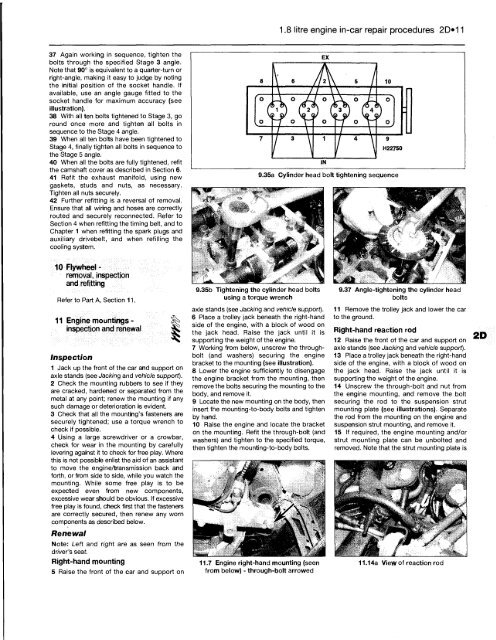
7 Working from below, unscrew the throughbolt<br />
(and washers) securing the engine<br />
bracket to the mounting (see illustration).<br />
8 Lower the engine sufficiently to disengage<br />
the engine bracket from the mounting, then<br />
remove the bolts securing the mounting to the<br />
body, and remove it.<br />
9 Locate the new mounting on the body, then<br />
insert the mounting-to-body bolts and tighten<br />
by hand.<br />
10 Raise the engine and locate the bracket<br />
on the mounting. Refit the through-bolt (and<br />
washers) and tighten to the specified torque,<br />
then tighten the mounting-to-body bolts.<br />
11.7 Engine right-hand mounting (seen<br />
from below) - through-bolt arrowed<br />
9.37 Angle-tightening the cylinder head<br />
bolts<br />
11 Remove the trolley jack and lower the car<br />
to the ground.<br />
Right-hand reaction rod<br />
12 Raise the front of the car and support on<br />
axle stands (see Jacking and vehicle support).<br />
13 Place a trolley jack beneath the right-hand<br />
side of the engine, with a block of wood on<br />
the jack head. Raise the jack until it is<br />
supporting the weight of the engine.<br />
14 Unscrew the through-bolt and nut from<br />
the engine mounting, and remove the bolt<br />
securing the rod to the suspension strut<br />
mounting plate (see illustrations). Separate<br />
the rod from the mounting on the engine and<br />
suspension strut mounting, and remove it.<br />
15 If required, the engine mounting and/or<br />
strut mounting plate can be unbolted and<br />
removed. Note that the strut mounting plate is<br />
11.14a View of reaction rod


