

Bravo & Brava • 1995 To 2000
Bravo & Brava • 1995 To 2000
Bravo & Brava • 1995 To 2000

You also want an ePaper? Increase the reach of your titles
YUMPU automatically turns print PDFs into web optimized ePapers that Google loves.
2.3a Remove the front section of the<br />
wheelarch liner ...<br />
. Lubricant is circulated under pressure by a<br />
gear-type pump, driven via an auxiliary shaft<br />
which itself is driven by the timing belt. Oil is<br />
drawn from the sump through a strainer, and<br />
then forced through an externally-mounted,<br />
replaceable screw-on filter. From there, it is<br />
distributed to the cylinder head, where it<br />
lubricates the camshaft journals and tappets,<br />
and also to the crankcase, where it lubricates<br />
the main bearings, connecting rod big and<br />
small-ends, gudgeon pins and cylinder bores.<br />
Models from 1999 onwards may be fitted<br />
with the revised 'Step A' engine, which<br />
features a number of minor modifications. The<br />
engine seen in our 1.6 litre project vehicle was<br />
a Step A engine.<br />
Repair operations possible with<br />
the engine in the car<br />
The following work can be carried out with<br />
the engine in the car:<br />
2.4 Remove the screw securing the timing<br />
belt upper access cover<br />
2.6 Using a dial gauge and probe to<br />
establish TDC on No 1 piston<br />
2.3b ... for access to the inner panel's<br />
front securing screw<br />
a) Auxiliary drivebelts - removal and refitting<br />
(see Chapter 1).<br />
b) Camshafts - removal and refitting.<br />
c) Camshaft oil seals - renewal.<br />
d) Auxiliary shaft oil seal - renewal.<br />
e) Camshaft sprockets - removal and refitting.<br />
f) Coolant pump - removal and refitting<br />
(refer to Chapter 3).<br />
g) Crankshaft oil seals - renewal.<br />
h) Crankshaft sprocket - removal and<br />
refitting.<br />
i) Cylinder head - removal and refitting.<br />
j) Engine mountings - inspection and renewal,<br />
k) Oil pump and pickup assembly - removal<br />
and refitting.<br />
I) Sump.<br />
m) Timing belt, sprockets and cover -<br />
removal, inspection and refitting.<br />
Note: It is possible to remove the pistons and<br />
connecting rods (after removing the cylinder<br />
head and sump) without removing the engine.<br />
However, this is not recommended. Work of<br />
this nature is more easily and thoroughly<br />
completed with the engine on the bench, as<br />
described in Chapter 2E.<br />
2 Location of TDC on<br />
No 1 cylinder J§<br />
1 With the car parked on a level surface, apply<br />
the handbrake and chock the rear wheels.<br />
Loosen the right-hand front wheel bolts.<br />
2 Raise the front of the vehicle, rest it<br />
securely on axle stands and remove the righthand<br />
front roadwheel.<br />
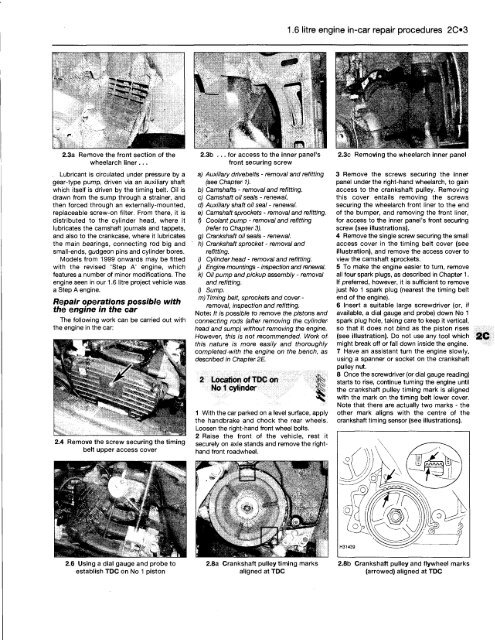
2.8a Crankshaft pulley timing marks<br />
aligned at TDC<br />
1.6 litre engine in-car repair procedures 203<br />
2.3c Removing the wheelarch inner panel<br />
3 Remove the screws securing the inner<br />
panel under the right-hand wheelarch, to gain<br />
access to the crankshaft pulley. Removing<br />
this cover entails removing the screws<br />
securing the wheelarch front liner to the end<br />
of the bumper, and removing the front liner,<br />
for access to the inner panel's front securing<br />
screw (see illustrations).<br />
4 Remove the single screw securing the small<br />
access cover in the timing belt cover (see<br />
illustration), and remove the access cover to<br />
view the camshaft sprockets.<br />
5 <strong>To</strong> make the engine easier to turn, remove<br />
all four spark plugs, as described in Chapter 1.<br />
If preferred, however, it is sufficient to remove<br />
just No 1 spark plug (nearest the timing belt<br />
end of the engine).<br />
6 Insert a suitable large screwdriver (or, if<br />
available, a dial gauge and probe) down No 1<br />
spark plug hole, taking care to keep it vertical,<br />
so that it does not bind as the piston rises<br />
(see illustration). Do not use any tool which<br />
might break off or fall down inside the engine.<br />
7 Have an assistant turn the engine slowly,<br />
using a spanner or socket on the crankshaft<br />
pulley nut.<br />
8 Once the screwdriver (or dial gauge reading)<br />
starts to rise, continue turning the engine until<br />
the crankshaft pulley timing mark is aligned<br />
with the mark on the timing belt lower cover.<br />
Note that there are actually two marks - the<br />
other mark aligns with the centre of the<br />
crankshaft timing sensor (see illustrations).<br />
2.8b Crankshaft pulley and flywheel marks<br />
(arrowed) aligned at TDC


