

Bravo & Brava • 1995 To 2000
Bravo & Brava • 1995 To 2000
Bravo & Brava • 1995 To 2000

You also want an ePaper? Increase the reach of your titles
YUMPU automatically turns print PDFs into web optimized ePapers that Google loves.
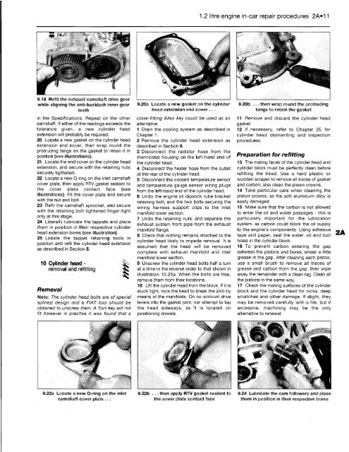
9.18 Refit the exhaust camshaft drive gear<br />
while aligning the anti-backlash inner gear<br />
teeth<br />
in the Specifications. Repeat on the other<br />
camshaft. If either of the readings exceeds the<br />
tolerance given, a new cylinder head<br />
extension will probably be required.<br />
20 Locate a new gasket on the cylinder head<br />
extension end cover, then wrap round the<br />
protruding tangs on the gasket to retain it in<br />
position (see illustrations).<br />
21 Locate the end cover on the cylinder head<br />
extension, and secure with the retaining nuts<br />
securely tightened.<br />
22 Locate a new O-ring on the inlet camshaft<br />
cover plate, then apply RTV gasket sealant to<br />
the cover plate contact face (see<br />
illustrations). Fit the cover plate and secure<br />
with the nut and bolt.<br />
23 Refit the camshaft sprocket, and secure<br />
with the retaining bolt tightened finger-tight<br />
only at this stage.<br />
24 Liberally lubricate the tappets and place<br />
them in position in their respective cylinder<br />
head extension bores (see illustration).<br />
25 Locate the tappet retaining tools in<br />
position and refit the cylinder head extension<br />
as described in Section 8.<br />
10 Cylinder head - ^<br />
removal and refitting S<br />
Removal<br />
Note: The cylinder head bolts are of special<br />
splined design and a FIAT tool should be<br />
obtained to unscrew them. A <strong>To</strong>ry, key will not<br />
fit however in practise it was found that a<br />
9.22a Locate a new O-ring on the inlet<br />
camshaft cover plate ...<br />
9.20a Locate a new gasket on the cylinder<br />
head extension end cover ...<br />
close-fitting Allen key could be used as an<br />
alternative.<br />
1 Drain the cooling system as described in<br />
Chapter 1.<br />
2 Remove the cylinder head extension as<br />
described in Section 8.<br />
3 Disconnect the radiator hose from the<br />
thermostat housing on the left-hand end of<br />
the cylinder head.<br />
4 Disconnect the heater hose from the outlet<br />
at the rear of the cylinder head.<br />
5 Disconnect the coolant temperature sensor<br />
and temperature gauge sensor wiring plugs<br />
from the left-hand end of the cylinder head.<br />
6 Undo the engine oil dipstick tube bracket<br />
retaining bolt, and the two bolts securing the<br />
wiring harness support clips to the inlet<br />
manifold lower section.<br />
7 Undo the retaining nuts, and separate the<br />
exhaust system front pipe from the exhaust<br />
manifold flange.<br />
8 Check that nothing remains attached to the<br />
cylinder head likely to impede removal. It is<br />
assumed that the head will be removed<br />
complete with exhaust manifold and inlet<br />
manifold lower section.<br />
9 Unscrew the cylinder head bolts half a turn<br />
at a time in the reverse order to that shown in<br />
illustration 10.25a. When the bolts are free,<br />
remove them from their locations..<br />
10 Lift the cylinder head from the block. If it is<br />
stuck tight, rock the head to break the joint by<br />
means of the manifolds. On no account drive<br />
levers into the gasket joint, nor attempt to tap<br />
the head sideways, as It is located on<br />
positioning dowels.<br />
i <strong>•</strong> <strong>•</strong><br />
* \<br />
9.22b ... then apply RTV gasket sealant to<br />
the cover plate contact face<br />
1.2 litre engine in-car repair procedures 2A«11<br />
9.20b ... then wrap round the protruding<br />
tangs to retain the gasket<br />
11 Remove and discard the cylinder head<br />
gasket.<br />
12 If necessary, refer to Chapter 2E for<br />
cylinder head dismantling and inspection<br />
procedures.<br />
Preparation for refitting<br />
13 The mating faces of the cylinder head and<br />
cylinder block must be perfectly clean before<br />
refitting the head. Use a hard plastic or<br />
wooden scraper to remove all traces of gasket<br />
and carbon; also clean the piston crowns.<br />
14 Take particular care when cleaning the<br />
piston crowns, as the soft aluminium alloy is<br />
easily damaged.<br />
15 Make sure that the carbon is not allowed<br />
to enter the oil and water passages - this is<br />
particularly important for the lubrication<br />
system, as carbon could block the oil supply<br />
to the engine's components. Using adhesive<br />
tape and paper, seal the water, oil and bolt<br />
holes in the cylinder block.<br />
16 <strong>To</strong> prevent carbon entering the gap<br />
between the pistons and bores, smear a little<br />
grease in the gap. After cleaning each piston,<br />
use a small brush to remove all traces of<br />
grease and carbon from the gap, then wipe<br />
away the remainder with a clean rag. Clean all<br />
the pistons in the same way.<br />
17 Check the mating surfaces of the cylinder<br />
block and the cylinder head for nicks, deep<br />
scratches and other damage. If slight, they<br />
may be removed carefully with a file, but if<br />
excessive, machining may be the only<br />
alternative to renewal.<br />
9.24 Lubricate the cam followers and place<br />
them in position in their respective bores


