

Bravo & Brava • 1995 To 2000
Bravo & Brava • 1995 To 2000
Bravo & Brava • 1995 To 2000

Create successful ePaper yourself
Turn your PDF publications into a flip-book with our unique Google optimized e-Paper software.
12*14 Body electrical systems<br />
1860897000<br />
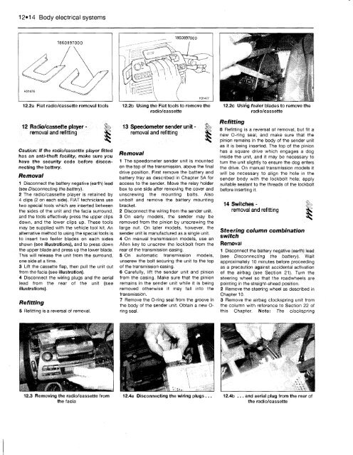
12.2a Fiat radio/cassette removal tools<br />
12 Radio/cassette player - |§><br />
removal and refitting ^<br />
Caution: If the radio/cassette player fitted<br />
has an anti-theft facility, make sure you<br />
have the security code before disconnecting<br />
the battery.<br />
Removal<br />
1 Disconnect the battery negative (earth) lead<br />
(see Disconnecting the battery).<br />
2 The radio/cassette player is retained by<br />
4 clips (2 on each side). FIAT technicians use<br />
two special tools which are inserted between<br />
the sides of the unit and the facia surround,<br />
and the tools effectively press the upper clips<br />
down, and the lower clips up. These tools<br />
may be supplied with the vehicle tool kit. An<br />
alternative method to using the special tools is<br />
to insert two feeler blades on each sides<br />
shown (see illustrations), and to press down<br />
the upper blade and press up the lower blade.<br />
This will release the unit from the surround,<br />
one side at a time.<br />
3 Lift the cassette flap, then pull the unit out<br />
from the facia (see illustration).<br />
4 Disconnect the wiring plugs and the aerial<br />
lead from the rear of the unit (see<br />
illustrations).<br />
Refitting<br />
5 Refitting is a reversal of removal.<br />
12.3 Removing the radio/cassette from<br />
the facia<br />
1860897000<br />
12.2b Using the Fiat tools to remove the<br />
radio/cassette<br />
13 Speedometer sender unit- %<br />
removal and refitting SK;<br />
Removal<br />
1 The speedometer sender unit is mounted<br />
on the top of the transmission, above the final<br />
drive position. First remove the battery and<br />
battery tray as described in Chapter 5A for<br />
access to the sender. Move the relay holder<br />
box to one side after removing the cover and<br />
unscrewing the mounting bolts. Also<br />
unbolt and remove the battery mounting<br />
bracket.<br />
2 Disconnect the wiring from the sender unit.<br />
3 On early models, the sender may be<br />
removed from the pinion by unscrewing the<br />
large nut. On later models, however, the<br />
sender unit is manufactured as a single unit.<br />
4 On manual transmission models, use an<br />
Allen key to unscrew the lockbolt from the<br />
rear of the transmission casing.<br />
5 On automatic transmission models,<br />
unscrew the bolt securing the unit to the top<br />
of the transmission casing.<br />
6 Carefully, lift the sender unit and pinion<br />
from the casing. Make sure that the pinion<br />
remains in the sender unit while it is being<br />
removed otherwise it may fall into the<br />
transmission.<br />
7 Remove the O-ring seal from the groove in<br />
the body of the sender unit. Obtain a new Oring<br />
seal.<br />
12.4a Disconnecting the wiring plugs ...<br />
12.2c Using feeler blades to remove the<br />
radio/cassette<br />
Refitting<br />
8 Refitting is a reversal of removal, but fit a<br />
new O-ring seal, and make sure that the<br />
pinion remains in the body of the sender unit<br />
as it is being inserted. The top of the pinion<br />
has a square drive which engages a dog<br />
inside the unit, and it may be necessary to<br />
turn the unit slightly to ensure the dog enters<br />
the drive. On manual transmission models it<br />
will be necessary to align the hole in the<br />
sender body with the lockbolt hole; apply<br />
suitable sealant to the threads of the lockbolt<br />
before inserting it.<br />
14 Switches - ^<br />
removal and refitting<br />
Steering column combination<br />
switch<br />
Removal<br />
1 Disconnect the battery negative (earth) lead<br />
(see Disconnecting the battery). Wait<br />
approximately 10 minutes before proceeding<br />
as a precaution against accidental activation<br />
of the airbag (see Section 21). Turn the<br />
steering wheel so that the roadwheels are<br />
pointing in the straight-ahead position.<br />
2 Remove the steering wheel as described in<br />
Chapter 10.<br />
3 Remove the airbag clockspring unit from<br />
the column with reference to Section 22 of<br />
this Chapter. Note: The clockspring<br />
12.4b ... and aerial plug from the rear of<br />
the radio/cassette


