

Bravo & Brava • 1995 To 2000
Bravo & Brava • 1995 To 2000
Bravo & Brava • 1995 To 2000

Create successful ePaper yourself
Turn your PDF publications into a flip-book with our unique Google optimized e-Paper software.
9»12 Braking system<br />
K-0<br />
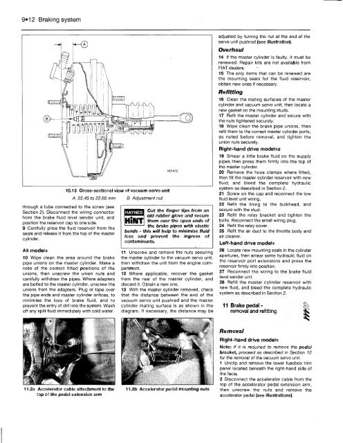
10.13 Cross-sectional view of vacuum servo unit<br />
through a tube connected to the screw (see<br />
Section 2). Disconnect the wiring connector<br />
from the brake fluid level sender unit, and<br />
position the reservoir cap to one side.<br />
9 Carefully prise the fluid reservoir from the<br />
seals and release it from the top of the master<br />
cylinder.<br />
All models<br />
10 Wipe clean the area around the brake<br />
pipe unions on the master cylinder. Make a<br />
note of the correct fitted positions of the<br />
unions, then unscrew the union nuts and<br />
carefully withdraw the pipes. Where adapters<br />
are bolted to the master cylinder, unscrew the<br />
unions from the adapters. Plug or tape over<br />
the pipe ends and master cylinder orifices, to<br />
minimise the loss of brake fluid, and to<br />
prevent the entry of dirt into the system. Wash<br />
off any spilt fluid immediately with cold water.<br />
11.2a Accelerator cable attachment to the<br />
top of the pedal extension arm<br />
A 22.45 to 22.65 mm B Adjustment nut<br />
HAYNES<br />
Cut the finger tips from an<br />
old rubber glove and secure<br />
them over the open ends of<br />
the brake pipes with elastic<br />
bands - this will help to minimise fluid<br />
loss and prevent the ingress of<br />
contaminants.<br />
11 Unscrew and remove the nuts securing<br />
the master cylinder to the vacuum servo unit,<br />
then withdraw the unit from the engine compartment.<br />
12 Where applicable, recover the gasket<br />
from the rear of the master cylinder, and<br />
discard it. Obtain a new one.<br />
13 With the master cylinder removed, check<br />
that the distance between the end of the<br />
vacuum servo unit pushrod and the master<br />
cylinder mating surface is as shown in the<br />
diagram. If necessary, the distance may be<br />
11.2b Accelerator pedal mounting nuts<br />
adjusted by turning the nut at the end of the<br />
servo unit pushrod (see illustration).<br />
Overhaul<br />
14 If the master cylinder is faulty, it must be<br />
renewed. Repair kits are not available from<br />
FIAT dealers.<br />
15 The only items that can be renewed are<br />
the mounting seals for the fluid reservoir;<br />
obtain new ones if necessary.<br />
Refitting<br />
16 Clean the mating surfaces of the master<br />
cylinder and vacuum servo unit, then locate a<br />
new gasket on the mounting studs.<br />
17 Refit the master cylinder and secure with<br />
the nuts tightened securely.<br />
18 Wipe clean the brake pipe unions, then<br />
refit them to the correct master cylinder ports,<br />
as noted before removal, and tighten the<br />
union nuts securely.<br />
Right-hand drive modelsz<br />
19 Smear a little brake fluid on the supply<br />
pipes then press them firmly into the top of<br />
the master cylinder.<br />
20 Remove the hose clamps where fitted,<br />
then fill the master cylinder reservoir with new<br />
fluid, and bleed the complete hydraulic<br />
system as described in Section 2.<br />
21 Screw on the cap and reconnect the low<br />
fluid level unit wiring.<br />
22 Refit the lining to the bulkhead, and<br />
secure with the stud.<br />
23 Refit the relay bracket and tighten the<br />
bolts. Reconnect the small wiring plug.<br />
24 Refit the relay cover.<br />
25 Refit the air duct to the throttle body and<br />
air cleaner.<br />
Left-hand drive models<br />
26 Locate new mounting seals in the cylinder<br />
apertures, then smear some hydraulic fluid on<br />
the reservoir port extensions and press the<br />
reservoir firmly into position.<br />
27 Reconnect the wiring to the brake fluid<br />
level sender unit.<br />
28 Refill the master cylinder reservoir with<br />
new fluid, and bleed the complete hydraulic<br />
system as described in Section 2.<br />
11 Brake pedalremoval<br />
and refitting<br />
Removal<br />
Right-hand drive models<br />


