

Bravo & Brava • 1995 To 2000
Bravo & Brava • 1995 To 2000
Bravo & Brava • 1995 To 2000

Create successful ePaper yourself
Turn your PDF publications into a flip-book with our unique Google optimized e-Paper software.
Note 1: It is possible to remove the pistons<br />
and connecting rods (after removing the<br />
cylinder head and sump) without removing the<br />
engine. However, this is not recommended.<br />
Work of this nature is more easily and<br />
thoroughly completed with the engine on the<br />
bench, as described in Chapter 2E.<br />
Note 2: Many of the procedures in this<br />
Chapter entail the use of numerous special<br />
tools. Where possible, suitable alternatives are<br />
described with details of their fabrication.<br />
Before starting any operations on the engine,<br />
read through the entire procedure first to<br />
familiarise yourself with the work involved,<br />
tools to be obtained and new parts that may<br />
be necessary.<br />
2 Engine assembly/<br />
valve timing holes -<br />
general information and usage<br />
Note: Do not attempt to rotate the engine<br />
whilst the camshafts are locked in position. If<br />
the engine is to be left in this state for a long<br />
period of time, it is a good idea to place<br />
suitable warning notices inside the vehicle,<br />
and in the engine compartment. This will<br />
reduce the possibility of the engine being<br />
accidentally cranked on the starter motor,<br />
which is likely to cause damage with the<br />
locking tools in place.<br />
1 <strong>To</strong> accurately set the valve timing for all<br />
operations requiring removal and refitting of<br />
the timing belt, timing holes are drilled in the<br />
camshafts and cylinder head extension. The<br />
holes are used in conjunction with camshaft<br />
locking tools and crankshaft positioning rods<br />
to lock the camshafts when all the pistons are<br />
positioned at the mid-point of their stroke.<br />
This arrangement prevents the possibility of<br />
the valves contacting the pistons when<br />
refitting the cylinder head or timing belt, and<br />
also ensures that the correct valve timing can<br />
be obtained. The design of the engine is such<br />
that there are no conventional timing marks<br />
on the crankshaft or camshaft sprockets to<br />
indicate the normal TDC position. Therefore,<br />
for any work on the timing belt, camshafts or<br />
cylinder head, the locking and positioning<br />
tools must be used.<br />
2 The special FIAT tools for setting the<br />
camshafts and pistons consist of two rods<br />
which slide in sleeves that are screwed into<br />
No 1 and No 2 cylinder spark plug holes. The<br />
rods are pushed down to contact the pistons,<br />
and the crankshaft is then turned until both<br />
rods protrude from their sleeves by the same<br />
amount. With the crankshaft correctly set,<br />
two camshaft locking pins are used, one for<br />
the inlet camshaft and one for the exhaust<br />
camshaft. The pins are screwed into holes on<br />
each side of the cylinder head extension so<br />
that they engage with slots machined in the<br />
camshafts. The arrangement of the FIAT<br />
special tools are shown (see illustrations).<br />
The tool numbers are as follows:<br />
1.2 litre engine in-car repair procedures 2A«3<br />
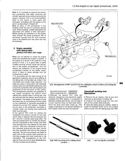
2.2a Arrangement of FIAT special tools for setting the piston position and locking the<br />
camshafts<br />
Camshaft locking tools - 1860985000<br />
Piston positioning tool - 186099<strong>2000</strong><br />
3 Although the special FIAT tools are<br />
relatively inexpensive and should be readily<br />
available from FIAT dealers, it is possible to<br />
fabricate suitable alternatives, with the help of<br />
a local machine shop, as described below.<br />
Once the tools have been made up, their<br />
usage is described in the relevant Sections of<br />
this Chapter where the tools are required.<br />
2.2b FIAT special tool for setting piston<br />
position ...<br />
Camshaft locking tool<br />
fabrication<br />
4 Remove the air cleaner, inlet air duct and<br />
resonator as described in Chapter 4B.<br />
5 Unscrew the sealing plug from the front<br />
face of the cylinder head extension.<br />
6 Using the sealing plug as a pattern, obtain a<br />
length of threaded dowel rod or two suitable<br />
bolts to screw into the sealing plug hole. With<br />
2.2c ... and locking the camshafts


