

Bravo & Brava • 1995 To 2000
Bravo & Brava • 1995 To 2000
Bravo & Brava • 1995 To 2000

Create successful ePaper yourself
Turn your PDF publications into a flip-book with our unique Google optimized e-Paper software.
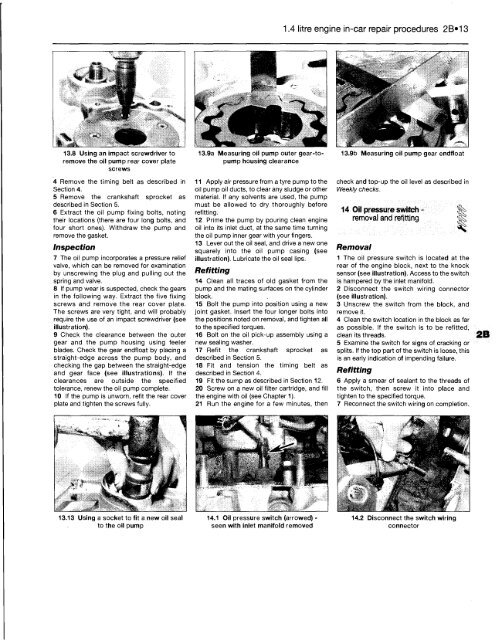
13.8 Using an impact screwdriver to<br />
remove the oil pump rear cover plate<br />
screws<br />
4 Remove the timing belt as described in<br />
Section 4.<br />
5 Remove the crankshaft sprocket as<br />
described in Section 5.<br />
6 Extract the oil pump fixing bolts, noting<br />
their locations (there are four long bolts, and<br />
four short ones). Withdraw the pump and<br />
remove the gasket.<br />
Inspection<br />
7 The oil pump incorporates a pressure relief<br />
valve, which can be removed for examination<br />
by unscrewing the plug and pulling out the<br />
spring and valve.<br />
8 If pump wear is suspected, check the gears<br />
in the following way. Extract the five fixing<br />
screws and remove the rear cover plate.<br />
The screws are very tight, and will probably<br />
require the use of an impact screwdriver (see<br />
illustration).<br />
9 Check the clearance between the outer<br />
gear and the pump housing using feeler<br />
blades. Check the gear endfloat by placing a<br />
straight-edge across the pump body, and<br />
checking the gap between the straight-edge<br />
and gear face (see illustrations). If the<br />
clearances are outside the specified<br />
tolerance, renew the oil pump complete.<br />
10 If the pump is unworn, refit the rear cover<br />
plate and tighten the screws fully.<br />
13.13 Using a socket to fit a new oil seal<br />
to the oil pump<br />
13.9a Measuring oil pump outer gear-topump<br />
housing clearance<br />
11 Apply air pressure from a tyre pump to the<br />
011 pump oil ducts, to clear any sludge or other<br />
material. If any solvents are used, the pump<br />
must be allowed to dry thoroughly before<br />
refitting.<br />
12 Prime the pump by pouring clean engine<br />
oil into its inlet duct, at the same time turning<br />
the oil pump inner gear with your fingers.<br />
13 Lever out the oil seal, and drive a new one<br />
squarely into the oil pump casing (see<br />
illustration). Lubricate the oil seal lips.<br />
Refitting<br />
14 Clean all traces of old gasket from the<br />
pump and the mating surfaces on the cylinder<br />
block.<br />
15 Bolt the pump into position using a new<br />
joint gasket. Insert the four longer bolts into<br />
the positions noted on removal, and tighten all<br />
to the specified torques.<br />
16 Bolt on the oil pick-up assembly using a<br />
new sealing washer.<br />
17 Refit the crankshaft sprocket as<br />
described in Section 5.<br />
18 Fit and tension the timing belt as<br />
described in Section 4.<br />
19 Fit the sump as described in Section 12.<br />
20 Screw on a new oil filter cartridge, and fill<br />
the engine with oil (see Chapter 1).<br />
21 Run the engine for a few minutes, then<br />
14.1 Oil pressure switch (arrowed) -<br />
seen with inlet manifold removed<br />
1.4 litre engine in-car repair procedures 2B»13<br />
13.9b Measuring oil pump gear endfloat<br />
check and top-up the oil level as described in<br />
Weekly checks.<br />
14 Oil pressure switch -<br />
removal and refitting 1<br />
Removal<br />
1 The oil pressure switch is located at the<br />
rear of the engine block, next to the knock<br />
sensor (see illustration). Access to the switch<br />
is hampered by the inlet manifold.<br />
2 Disconnect the switch wiring connector<br />
(see illustration).<br />
3 Unscrew the switch from the block, and<br />
remove it.<br />
4 Clean the switch location in the block as far<br />
as possible. If the switch is to be refitted,<br />
clean its threads.<br />
5 Examine the switch for signs of cracking or<br />
splits. If the top part of the switch is loose, this<br />
is an early indication of impending failure.<br />
Refitting<br />
6 Apply a smear of sealant to the threads of<br />
the switch, then screw it into place and<br />
tighten to the specified torque.<br />
7 Reconnect the switch wiring on completion.<br />
14.2 Disconnect the switch wiring<br />
connector


