

Bravo & Brava • 1995 To 2000
Bravo & Brava • 1995 To 2000
Bravo & Brava • 1995 To 2000

You also want an ePaper? Increase the reach of your titles
YUMPU automatically turns print PDFs into web optimized ePapers that Google loves.
2A»12 1.2 litre engine in-car repair procedures<br />
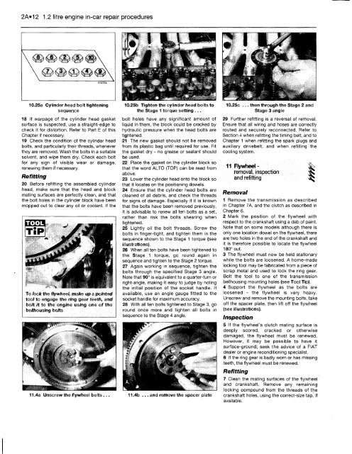
10.25a Cylinder head bolt tightening<br />
sequence<br />
18 If warpage of the cylinder head gasket<br />
surface, is suspected, use a straight-edge to<br />
check it for distortion. Refer to Part E of this<br />
Chapter if necessary,<br />
19 Check the condition of the cylinder head<br />
bolts, and particularly their threads, whenever<br />
they are removed. Wash the bolts in a suitable<br />
solvent, and wipe them dry. Check each bolt<br />
for any sign of visible wear or damage,<br />
renewing them if necessary.<br />
Refitting<br />
20 Before refitting the assembled cylinder<br />
head, make sure that the head and block<br />
mating surfaces are perfectly clean, and that<br />
the bolt holes in the cylinder block have been<br />
mopped out to clear any oil or coolant. If the<br />
<strong>To</strong> lock the flywheel, make up a pointed<br />
tool to engage the ring gear teeth, and<br />
bolt it to the engine using one of the<br />
bellhousing bolts<br />
11.4a Unscrew the flywheel bolts ..<br />
10.25b Tighten the cylinder head bolts<br />
the Stage 1 torque setting ...<br />
bolt holes have any significant amount of<br />
liquid in them, the block could be cracked by<br />
hydraulic pressure when the head bolts are<br />
tightened.<br />
21 The new gasket should not be removed<br />
from its plastic bag until required for use. Fit<br />
the gasket dry - no grease or sealant should<br />
be used.<br />
22 Place the gasket on the cylinder block so<br />
that the word ALTO (TOP) can be read from<br />
above.<br />
23 Lower the cylinder head onto the block so<br />
that it locates on the positioning dowels.<br />
24 Ensure that the cylinder head bolts are<br />
cleaned of all debris, and check the threads<br />
for signs of damage. Especially if it is known<br />
that the bolts have been removed previously,<br />
it is advisable to renew all ten botts as a set,<br />
rather than risk the bolts shearing when<br />
tightened.<br />
25 Lightly oil the bolt threads. Screw the<br />
bolts in finger-tight, and tighten them in the<br />
sequence shown to the Stage 1 torque (see<br />
illustrations).<br />
26 When all ten bolts have been tightened to<br />
the Stage 1 torque, go round again in<br />
sequence and tighten to the Stage 2 torque.<br />
27 Again working in sequence, tighten the<br />
bolts through the specified Stage 3 angle.<br />
Note that 90° is equivalent to a quarter-turn or<br />
right-angle, making it easy to judge by noting<br />
the initial position of the socket handle. If<br />
available, use an angle gauge fitted to the<br />
socket handle for maximum accuracy.<br />
28 With all ten bolts tightened to Stage 3, go<br />
round once more and tighten all bolts in<br />
sequence to the Stage 4 angle.<br />
11.4b ... and remove the spacer plate<br />
10.25c ... then through the Stage 2 and<br />
Stage 3 angle<br />
29 Further refitting is a reversal of removal.<br />
Ensure that all wiring and hoses are correctly<br />
routed and securely reconnected. Refer to<br />
Section 4 when refitting the timing belt, and to<br />
Chapter 1 when refitting the spark plugs and<br />
auxiliary drivebelt, and when refilling the<br />
cooling system.<br />
11 Flywheel - ^<br />
removal, inspection S<br />
and refitting<br />
Removal<br />
1 Remove the transmission as described<br />
in Chapter 7A, and the clutch as described in<br />
Chapter 6.<br />
2 Mark the position of the flywheel with<br />
respect to the crankshaft using a dab of paint.<br />
Note that on some models although there is<br />
only one location dowel on the flywheel, there<br />
are two holes in the end of the crankshaft and<br />
it is therefore possible to locate the flywheel<br />
180° out.<br />
3 The flywheel must now be held stationary<br />
while the bolts are loosened. A home-made<br />
locking tool may be fabricated from a piece of<br />
scrap metal and used to lock the ring gear.<br />
Bolt the tool to one of the transmission<br />
bellhousing mounting holes (see <strong>To</strong>ol Tip).<br />
4 Support the flywheel as the bolts are<br />
loosened - the flywheel is very heavy.<br />
Unscrew and remove the mounting bolts, take<br />
off the spacer plate, then lift off the flywheel<br />
(see illustrations).<br />
Inspection<br />
5 If the flywheel's clutch mating surface is<br />
deeply scored, cracked or otherwise<br />
damaged, the flywheel must be renewed.<br />
However, it may be possible to have it<br />
surface-ground; seek the advice of a FIAT<br />
dealer or engine reconditioning specialist.<br />
6 If the ring gear is badly worn or has missing<br />
teeth, the flywheel must be renewed.<br />
Refitting<br />
7 Clean the mating surfaces of the flywheel<br />
and crankshaft. Remove any remaining<br />
locking compound from the threads of the<br />
crankshaft holes, using the correct-size tap, if<br />
available.


