

Bravo & Brava • 1995 To 2000
Bravo & Brava • 1995 To 2000
Bravo & Brava • 1995 To 2000

You also want an ePaper? Increase the reach of your titles
YUMPU automatically turns print PDFs into web optimized ePapers that Google loves.
4B»8 Fuel system - multi-point injection<br />
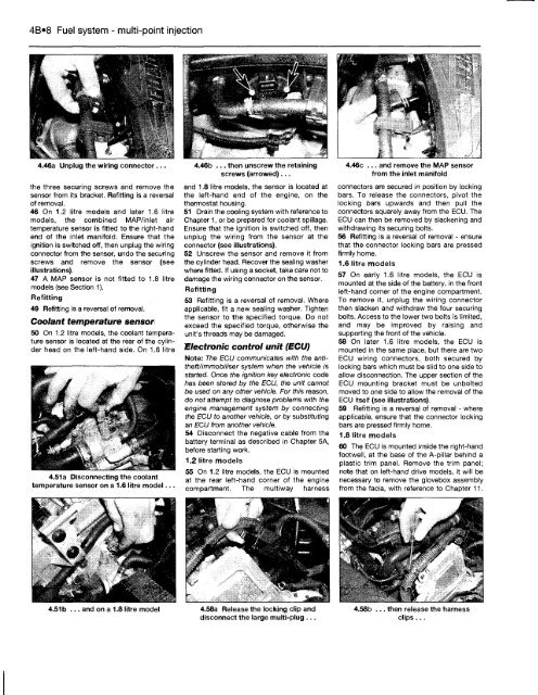
4.46a Unplug the wiring connector...<br />
the three securing screws and remove the<br />
sensor from its bracket. Refitting is a reversal<br />
of removal.<br />
46 On 1.2 litre models and later 1.6 litre<br />
models, the combined MAP/inlet air<br />
temperature sensor is fitted to the right-hand<br />
end of the inlet manifold. Ensure that the<br />
ignition is switched off, then unplug the wiring<br />
connector from the sensor, undo the securing<br />
screws and remove the sensor (see<br />
illustrations).<br />
47 A MAP sensor is not fitted to 1.8 litre<br />
models (see Section 1).<br />
Refitting<br />
49 Refitting is a reversal of removal.<br />
Coolant temperature sensor<br />
50 On 1.2 litre models, the coolant temperature<br />
sensor is located at the rear of the cylinder<br />
head on the left-hand side. On 1.6 litre<br />
4.51a Disconnecting the coolant<br />
temperature sensor on a 1.6 litre model.<br />
4.46b ... then unscrew the retaining<br />
screws (arrowed)...<br />
and 1.8 litre models, the sensor is located at<br />
the left-hand end of the engine, on the<br />
thermostat housing.<br />
51 Drain the cooling system with reference to<br />
Chapter 1, or be prepared for coolant spillage.<br />
Ensure that the ignition is switched off, then<br />
unplug the wiring from the sensor at the<br />
connector (see illustrations).<br />
52 Unscrew the sensor and remove it from<br />
the cylinder head. Recover the sealing washer<br />
where fitted. If using a socket, take care not to<br />
damage the wiring connector on the sensor.<br />
Refitting<br />
53 Refitting is a reversal of removal. Where<br />
applicable, fit a new sealing washer. Tighten<br />
the sensor to the specified torque. Do not<br />
exceed the specified torque, otherwise the<br />
unit's threads may be damaged.<br />
Electronic control unit (ECU)<br />
Note: The ECU communicates with the antitheft/immobiliser<br />
system when the vehicle is<br />
started. Once the ignition key electronic code<br />
has been stored by the ECU, the unit cannot<br />
be used on any other vehicle. For this reason,<br />
do not attempt to diagnose problems with the<br />
engine management system by connecting<br />
the ECU to another vehicle, or by substituting<br />
an ECU from another vehicle.<br />
54 Disconnect the negative cable from the<br />
battery terminal as described in Chapter 5A,<br />
before starting work.<br />
1.2 litre models<br />
55 On 1.2 litre models, the ECU is mounted<br />
at the rear left-hand corner of the engine<br />
compartment. The multiway harness<br />
4.51b ... and on a 1.8 litre model 4.58a Release the locking clip and<br />
disconnect the large multi-plug ...<br />
4.46c ... and remove the MAP sensor<br />
from the inlet manifold<br />
connectors are secured in position by locking<br />
bars. <strong>To</strong> release the connectors, pivot the<br />
locking bars upwards and then pull the<br />
connectors squarely away from the ECU. The<br />
ECU can then be removed by slackening and<br />
withdrawing its securing bolts.<br />
56 Refitting is a reversal of removal - ensure<br />
that the connector locking bars are pressed<br />
firmly home.<br />
1.6 litre models<br />
57 On early 1.6 litre models, the ECU is<br />
mounted at the side of the battery, in the front<br />
left-hand corner of the engine compartment.<br />
<strong>To</strong> remove it, unplug the wiring connector<br />
then slacken and withdraw the four securing<br />
bolts. Access to the lower two bolts is limited,<br />
and may be improved by raising and<br />
supporting the front of the vehicle.<br />
58 On later 1.6 litre models, the ECU is<br />
mounted in the same place, but there are two<br />
ECU wiring connectors, both secured by<br />
locking bars which must be slid to one side to<br />
allow disconnection. The upper section of the<br />
ECU mounting bracket must be unbolted<br />
moved to one side to allow the removal of the<br />
ECU itself (see illustrations).<br />
59 Refitting is a reversal of removal - where<br />
applicable, ensure that the connector locking<br />
bars are pressed firmly home.<br />
1.8 litre models<br />
60 The ECU is mounted inside the right-hand<br />
footwell, at the base of the A-pillar behind a<br />
plastic trim panel. Remove the trim panel;<br />
note that on left-hand drive models, it will be<br />
necessary to remove the glovebox assembly<br />
from the facia, with reference to Chapter 11.<br />
4.58b ... then release the harness<br />
clips...


