

Bravo & Brava • 1995 To 2000
Bravo & Brava • 1995 To 2000
Bravo & Brava • 1995 To 2000

Create successful ePaper yourself
Turn your PDF publications into a flip-book with our unique Google optimized e-Paper software.
4A»2 Fuel system - single-point injection<br />
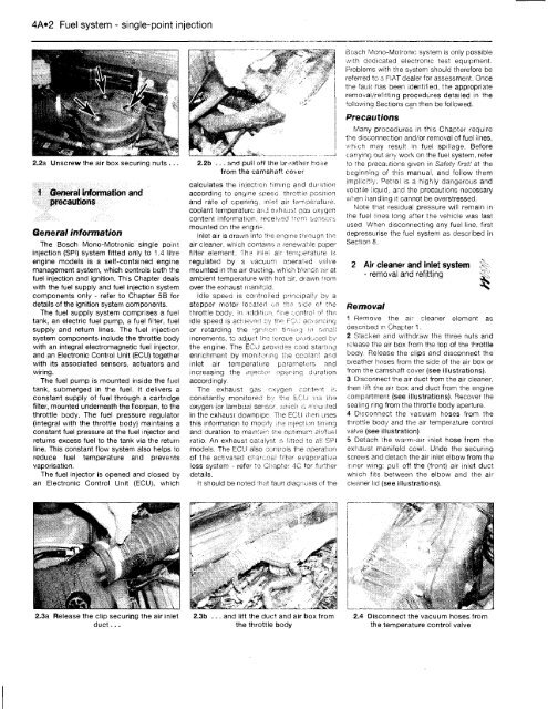
2.2a Unscrew the air box securing nuts ..<br />
1 General information and<br />
precautions<br />
General information<br />
The Bosch Mono-Motronic single point<br />
injection (SPI) system fitted only to 1.4 litre<br />
engine models is a self-contained engine<br />
management system, which controls both the<br />
fuel injection and ignition. This Chapter deals<br />
with the fuel supply and fuel injection system<br />
components only - refer to Chapter 5B for<br />
details of the ignition system components.<br />
The fuel supply system comprises a fuel<br />
tank, an electric fuel pump, a fuel filter, fuel<br />
supply and return lines. The fuel injection<br />
system components include the throttle body<br />
with an integral electromagnetic fuel injector,<br />
and an Electronic Control Unit (ECU) together<br />
with its associated sensors, actuators and<br />
wiring.<br />
The fuel pump is mounted inside the fuel<br />
tank, submerged in the fuel. It delivers a<br />
constant supply of fuel through a cartridge<br />
filter, mounted underneath the floorpan, to the<br />
throttle body. The fuel pressure regulator<br />
(integral with the throttle body) maintains a<br />
constant fuel pressure at the fuel injector and<br />
returns excess fuel to the tank via the return<br />
line. This constant flow system also helps to<br />
reduce fuel temperature and prevents<br />
vaporisation.<br />
The fuel injector is opened and closed by<br />
an Electronic Control Unit (ECU), which<br />
2.3a Release the clip securing the air inlet<br />
duct...<br />
2.2b ... and pull o*f tne brother hose<br />
from the camshaft cover<br />
calculates the injection timing and duration<br />
according to engine speed, throttle position<br />
and rate of opening, iniet air temperature,<br />
coolant temperature an.j exhaust gas oxygen<br />
content information, received from sensor;,<br />
mounted on the engine.<br />
Inlet air is drawn into the engine through the<br />
air cleaner, which contains a renewable paper<br />
filter element. The inle! air temperature is<br />
regulated by a vacuum operated valve<br />
mounted in the air ducting, which blends air at<br />
ambient temperature with hot air, drawn from<br />
over the exhaust manifold.<br />
Idle speed is controlled principally by a<br />
stepper motor located on the side of the<br />
throttle body. In addition, fine control of the<br />
idle speed is achieved Py the FCU acvaneing<br />
or retarding the -griiion timing in small<br />
increments, to adjust the torque produced by<br />
the engine. The ECU provides cold starting<br />
enrichment by monitoring the coolant and<br />
inlet air temperature parameters and<br />
increasing the injector opening duration<br />
accordingly.<br />
The exhaust gas oxygen content is<br />
constantly monitored by the ECU via the<br />
oxygen (or lambda) sensor, which is mounted<br />
in the exhaust downpipe. The ECU then uses<br />
this information to modify ihe injection timing<br />
and duration to maintain the optimum air/fuel<br />
ratio. An exhaust catalyst :s fitted to all SPI<br />
models. The ECU also controls the operation<br />
of the activated charcoal filter evaporative<br />
loss system - refer to Chapter 4C tor further<br />
details.<br />
It should be noted that fault diagnosis of the<br />
2.3b .. . and lift the duct and air box from<br />
the throttle body<br />
Bosch Mono-Motronic system is only possible<br />
with dedicated electronic test equipment.<br />
Problems with the system should therefore be<br />
referred to a FIAT dealer for assessment. Once<br />
the fauii has been identified, the appropriate<br />
removal/refitting procedures detailed in the<br />
following Sections can then be followed.<br />
Precautions<br />
Many procedures in this Chapter require<br />
the disconnection and/or removal of fuel lines,<br />
which may result in fuel spillage. Before<br />
carrying out any work on the fuel system, refer<br />
So the precautions given in Safety first! at the<br />
beginning of this manual, and follow them<br />
implicitly. Petrol is a highly dangerous and<br />
volatile liquid, and the precautions necessary<br />
when handling It cannot be overstressed.<br />
Note that residual pressure will remain in<br />
trie fuel lines long after the vehicle was last<br />
used When disconnecting any fuel line, first<br />
depressurise the fuel system as described in<br />
Section 8.<br />
Removal<br />
Air cleaner and inlet system<br />
- removal and refitting<br />
1 Remove the air cleaner element as<br />
described in Chapter 1.<br />
2 Slacken and withdraw the three nuts and<br />
release the air box from the top of the throttle<br />
body. Release the clips and disconnect the<br />
breather hoses from the side of the air box or<br />
from the camshaft cover (see illustrations).<br />
3 Disconnect the air duct from ihe air cleaner,<br />
then lift the air box and duct from the engine<br />
compartment (see illustrations). Recover the<br />
sealing ring from the throttle body aperture.<br />
4 Disconnect the vacuum hoses from the<br />
throttle body and the air temperature control<br />
valve (see illustration)<br />
5 Detach the warni-air inlet, hose from the<br />
exhaust manifold cowl. Undo the securing<br />
screws and detach the air inlet elbow from the<br />
Inner wing; pull off the (front) air inlet duct<br />
which fits between the elbow and the air<br />
cleaner lid (see illustrations).<br />
2.4 Disconnect the vacuum hoses from<br />
the temperature control valve


