

Bravo & Brava • 1995 To 2000
Bravo & Brava • 1995 To 2000
Bravo & Brava • 1995 To 2000

Create successful ePaper yourself
Turn your PDF publications into a flip-book with our unique Google optimized e-Paper software.
4A»6 Fuel system - single-point injection<br />
5.5 Disconnecting the charcoal canister<br />
hose at the inner wing<br />
4 Disconnect the accelerator cable inner from<br />
the remote throttle disc cam as described in<br />
Section 4, then disconnect the link rod from<br />
the spigot on the throttle disc cam.<br />
5 Disconnect the vacuum hoses that serve<br />
the EVAP purge valve and intake air flap valve<br />
from the throttle body. Alternatively, the EVAP<br />
5.6 Throttle body through-bolts (A), fuel<br />
pressure regulator screws (B) and injector<br />
securing screw (C)<br />
hose can be disconnected at the connector<br />
above the inner wing (see illustration).<br />
6 Slacken and remove the four through-bolts<br />
securing the throttle body assembly to the<br />
inlet manifold, then remove the assembly<br />
along with its insulating spacer (see<br />
illustration). Unless specifically required, it is<br />
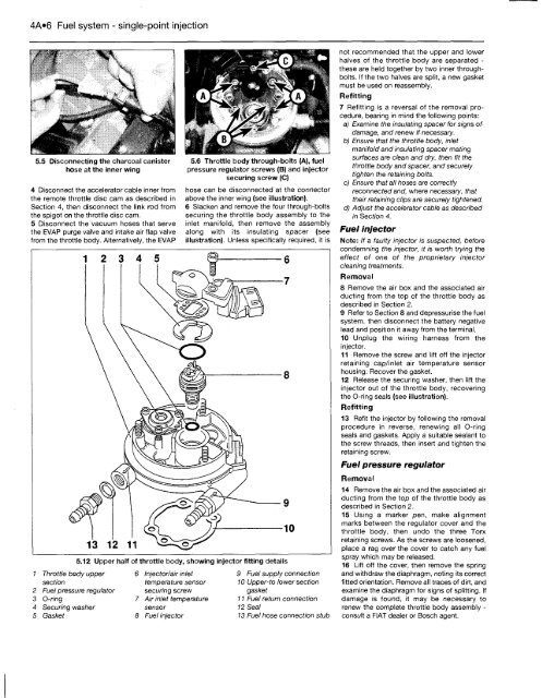
5.12 Upper half of throttle body, showing injector fitting details<br />
Throttle body upper<br />
section<br />
Fuel pressure regulator<br />
O-ring<br />
Securing washer<br />
Gasket<br />
6 Injector/air inlet<br />
temperature sensor<br />
securing screw<br />
Air inlet temperature<br />
sensor<br />
Fuel injector<br />
9 Fuel supply connection<br />
10 Upper-to lower section<br />
gasket<br />
11 Fuel return connection<br />
12 Seal<br />
13 Fuel hose connection stub<br />
not recommended that the upper and lower<br />
halves of the throttle body are separated -<br />
these are held together by two inner throughbolts.<br />
If the two halves are split, a new gasket<br />
must be used on reassembly.<br />
Refitting<br />
7 Refitting is a reversal of the removal procedure,<br />
bearing in mind the following points:<br />
a) Examine the insulating spacer for signs of<br />
damage, and renew if necessary.<br />
b) Ensure that the throttle body, inlet<br />
manifold and insulating spacer mating<br />
surfaces are clean and dry, then fit the<br />
throttle body and spacer, and securely<br />
tighten the retaining bolts.<br />
c) Ensure that all hoses are correctly<br />
reconnected and, where necessary, that<br />
their retaining clips are securely tightened.<br />
d) Adjust the accelerator cable as described<br />
in Section 4.<br />
Fuel injector<br />
Note: If a faulty injector is suspected, before<br />
condemning the injector, it is worth trying the<br />
effect of one of the proprietary injector<br />
cleaning treatments.<br />
Removal<br />
8 Remove the air box and the associated air<br />
ducting from the top of the throttle body as<br />
described in Section 2.<br />
9 Refer to Section 8 and depressurise the fuel<br />
system, then disconnect the battery negative<br />
lead and position it away from the terminal.<br />
10 Unplug the wiring harness from the<br />
injector.<br />
11 Remove the screw and lift off the injector<br />
retaining cap/inlet air temperature sensor<br />
housing. Recover the gasket.<br />
12 Release the securing washer, then lift the<br />
injector out of the throttle body, recovering<br />
the O-ring seals (see illustration).<br />
Refitting<br />
13 Refit the injector by following the removal<br />
procedure in reverse, renewing all O-ring<br />
seals and gaskets. Apply a suitable sealant to<br />
the screw threads, then insert and tighten the<br />
retaining screw.<br />
Fuel pressure regulator<br />
Removal<br />
14 Remove the air box and the associated air<br />
ducting from the top of the throttle body as<br />
described in Section 2.<br />
15 Using a marker pen, make alignment<br />
marks between the regulator cover and the<br />
throttle body, then undo the three <strong>To</strong>rx<br />
retaining screws. As the screws are loosened,<br />
place a rag over the cover to catch any fuel<br />
spray which may be released.<br />
16 Lift off the cover, then remove the spring<br />
and withdraw the diaphragm, noting its correct<br />
fitted orientation. Remove all traces of dirt, and<br />
examine the diaphragm for signs of splitting. If<br />
damage is found, it may be necessary to<br />
renew the complete throttle body assembly -<br />
consult a FIAT dealer or Bosch agent.


