

Bravo & Brava • 1995 To 2000
Bravo & Brava • 1995 To 2000
Bravo & Brava • 1995 To 2000

You also want an ePaper? Increase the reach of your titles
YUMPU automatically turns print PDFs into web optimized ePapers that Google loves.
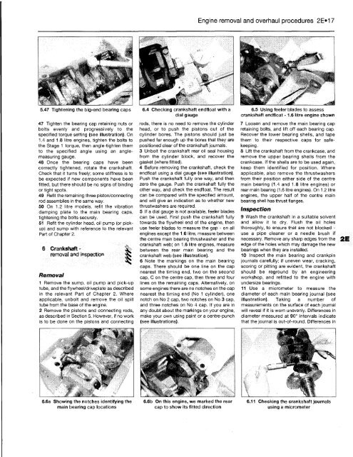
5.47 Tightening the big-end bearing caps<br />
47 Tighten the bearing cap retaining nuts or<br />
bolts evenly and progressively to the<br />
specified torque setting (see illustration). On<br />
1.4 and 1.8 litre engines, tighten the bolts to<br />
the Stage 1 torque, then angle-tighten them<br />
to the specified angle using an anglemeasuring<br />
gauge.<br />
48 Once the bearing caps have been<br />
correctly tightened, rotate the crankshaft.<br />
Check that it turns freely; some stiffness is to<br />
be expected if new components have been<br />
fitted, but there should be no signs of binding<br />
or tight spots.<br />
49 Refit the remaining three piston/connecting<br />
rod assemblies in the same way.<br />
50 On 1.2 litre models, refit the vibration<br />
damping plate to the main bearing caps,<br />
tightening the bolts securely.<br />
51 Refit the cylinder head, oil pump (or pickup)<br />
and sump with reference to the relevant<br />
Part of Chapter 2.<br />
6 Crankshaft -<br />
removal and inspection<br />
Removal<br />
1 Remove the sump, oil pump and pick-up<br />
tube, and the flywheel/driveplate as described<br />
in the relevant Part of Chapter 2. Where<br />
applicable, unbolt and remove the oil spill<br />
tube from the base of the engine.<br />
2 Remove the pistons and connecting rods,<br />
as described in Section 5. However, if no work<br />
is to be done on the pistons and connecting<br />
6.6a Showing the notches identifying the<br />
main bearing cap locations<br />
6.4 Checking crankshaft endfloat with a<br />
dial gauge<br />
rods, there is no need to remove the cylinder<br />
head, or to push the pistons out of the<br />
cylinder bores. The pistons should just be<br />
pushed far enough up the bores that they are<br />
positioned clear of the crankshaft journals.<br />
3 Unbolt the crankshaft rear oil seal housing<br />
from the cylinder block, and recover the<br />
gasket (where fitted).<br />
4 Before removing the crankshaft, check the<br />
endfloat using a dial gauge (see illustration).<br />
Push the crankshaft fully one way, and then<br />
zero the gauge. Push the crankshaft fully the<br />
other way, and check the endfloat. The result<br />
can be compared with the specified amount,<br />
and will give an indication as to whether new<br />
thrustwashers are required.<br />
5 If a dial gauge is not available, feeler blades<br />
can be used. First push the crankshaft fully<br />
towards the flywheel end of the engine, then<br />
use feeler blades to measure the gap - on all<br />
engines except the 1.6 litre, measure between<br />
the centre main bearing thrustwasher and the<br />
crankshaft web; on 1.6 litre engines, measure<br />
between the rear main bearing and the<br />
crankshaft web (see illustration).<br />
6 Note the markings on the main bearing<br />
caps. There should be one line on the cap<br />
nearest the timing end, two on the second<br />
cap, C on the centre cap, then three and four<br />
lines on the remaining caps. Alternatively, on<br />
some engines there are no notches on the cap<br />
nearest the timing end (No 1 cylinder), one<br />
notch on No 2 cap, two notches on No 3 cap,<br />
and three notches on No 4 cap. If you are in<br />
any doubt about the markings on your engine,<br />
make your own using paint or a centre-punch<br />
(see illustrations).<br />
6.6b On this engine, we marked the rear<br />
cap to show its fitted direction<br />
Engine removal and overhaul procedures 2E»17<br />
6.5 Using feeler blades to assess<br />
crankshaft endfloat -1.6 litre engine shown<br />
7 Loosen and remove the main bearing cap<br />
retaining bolts, and lift off each bearing cap.<br />
Recover the lower bearing shells, and tape<br />
them to their respective caps for safekeeping.<br />
8 Lift the crankshaft from the crankcase, and<br />
remove the upper bearing shells from the<br />
crankcase. If the shells are to be used again,<br />
keep them identified for position. Where<br />
applicable, also remove the thrustwashers<br />
from their position either side of the centre<br />
main bearing (1.4 and 1.8 litre engines) or<br />
rear main bearing (1.6 litre engines). On 1.2 litre<br />
engines, the upper half of the centre main<br />
bearing shell has thrust flanges.<br />
Inspection<br />
9 Wash the crankshaft in a suitable solvent<br />
and allow it to dry. Flush the oil holes<br />
thoroughly, to ensure that are not blocked -<br />
use a pipe cleaner or a needle brush if<br />
necessary. Remove any sharp edges from the<br />
edge of the holes which may damage the new<br />
bearings when they are installed.<br />
10 Inspect the main bearing and crankpin<br />
journals carefully; if uneven wear, cracking,<br />
scoring or pitting are evident, the crankshaft<br />
should be reground by an engineering<br />
workshop, and refitted to the engine with<br />
undersize bearings.<br />
11 Use a micrometer to measure the<br />
diameter of each main bearing journal (see<br />
illustration). Taking a number of<br />
measurements on the surface of each journal<br />
will reveal if it is worn unevenly. Differences in<br />
diameter measured at 90° intervals indicate<br />
that the journal is out-of-round. Differences in<br />
6.11 Checking the crankshaft journals<br />
using a micrometer


