

Bravo & Brava • 1995 To 2000
Bravo & Brava • 1995 To 2000
Bravo & Brava • 1995 To 2000

Create successful ePaper yourself
Turn your PDF publications into a flip-book with our unique Google optimized e-Paper software.
12<strong>•</strong> 12 Body electrical systems<br />
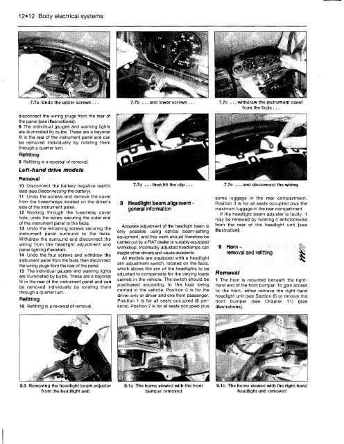
7.7a Undo the upper screws ...<br />
disconnect the wiring plugs from the rear of<br />
the panel (see illustrations).<br />
8 The individual gauges and warning lights<br />
are illuminated by bulbs. These are a bayonet<br />
fit in the rear of the instrument panel and can<br />
be removed individually by rotating them<br />
through a quarter turn.<br />
Refitting<br />
9 Refitting is a reversal of removal.<br />
Left-hand drive models<br />
Removal<br />
10 Disconnect the battery negative (earth)<br />
lead (see Disconnecting the battery).<br />
11 Undo the screws and remove the cover<br />
from the fuses/relays located on the driver's<br />
side of the instrument panel.<br />
12 Working through the fuse/relay cover<br />
hole, undo the screw securing the outer end<br />
of the instrument panel to the facia.<br />
13 Undo the remaining screws securing the<br />
instrument panel surround to the facia.<br />
Withdraw the surround and disconnect the<br />
wiring from the headlight adjustment and<br />
panel lighting rheostats.<br />
14 Undo the four screws and withdraw the<br />
instrument panel from the facia, then disconnect<br />
the wiring plugs from the rear of the panel.<br />
15 The individual gauges and warning lights<br />
are illuminated by bulbs. These are a bayonet<br />
fit in the rear of the instrument panel and can<br />
be removed individually by rotating them<br />
through a quarter turn.<br />
Refitting<br />
16 Refitting is a reversal of removal.<br />
8.3 Removing the headlight beam adjuster<br />
from the headlight unit<br />
7.7b ... and lower screws ...<br />
7.7d ... then lift the clip ...<br />
8 Headlight beam alignment -<br />
general information<br />
Accurate adjustment of the headlight beam is<br />
only possible using optical beam-setting<br />
equipment, and this work should therefore be<br />
carried out by a FIAT dealer or suitably-equipped<br />
workshop. Incorrectly adjusted headlamps can<br />
dazzle other drivers and cause accidents.<br />
All models are equipped with a headlight<br />
aim adjustment switch, located on the facia,<br />
which allows the aim of the headlights to be<br />
adjusted to compensate for the varying loads<br />
carried in the vehicle. The switch should be<br />
positioned according to the load being<br />
carried in the vehicle. Position 0 is for the<br />
driver only or driver and one front passenger.<br />
Position 1 is for all seats occupied (5 persons).<br />
Position 2 is for all seats occupied plus<br />
9.1a The horns viewed with the front<br />
bumper removed<br />
7.7c ... withdraw the instrument panel<br />
from the facia ...<br />
7.7e ... and disconnect the wiring<br />
some luggage in the rear compartment.<br />
Position 3 is for all seats occupied plus the<br />
maximum luggage in the rear compartment.<br />
If the headlight beam adjuster is faulty, it<br />
may be renewed by twisting it anticlockwise<br />
from the rear of the headlight unit (see<br />
illustration).<br />
9 Horn- 8^<br />
removal and refitting Sfc<br />
Removal<br />
1 The horn is mounted beneath the righthand<br />
end of the front bumper. <strong>To</strong> gain access<br />
to the horn, either remove the right-hand<br />
headlight unit (see Section 6) or remove the<br />
front bumper (see Chapter 11) (see<br />
illustrations).<br />
9.1b The horns viewed with the right-hand<br />
headlight unit removed


