

Bravo & Brava • 1995 To 2000
Bravo & Brava • 1995 To 2000
Bravo & Brava • 1995 To 2000

You also want an ePaper? Increase the reach of your titles
YUMPU automatically turns print PDFs into web optimized ePapers that Google loves.
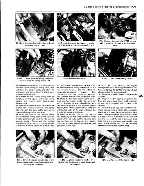
4.9 Undo the retaining bolt in the centre of<br />
the lower timing cover<br />
4.11b ... then slide the wiring plug and<br />
socket from the timing cover slot<br />
11 Release the crankshaft TDC sensor wiring<br />
from the clip on the upper timing cover, then<br />
withdraw the cover slightly and slide the<br />
wiring plug and socket from the timing cover<br />
slot (see illustrations).<br />
12 Release the TDC sensor wiring from the<br />
periphery of the upper and lower timing<br />
covers, and remove both covers (see<br />
illustrations).<br />
13 Free the accelerator inner cable from the<br />
throttle cam, remove the outer cable spring<br />
clip, then pull the outer cable out from its<br />
mounting bracket rubber grommet.<br />
14 From the side of the throttle body,<br />
disconnect the wiring connectors from the<br />
throttle potentiometer and the idle control<br />
stepper motor. Disconnect the coolant<br />
temperature sensor wiring connector located<br />
in the inlet manifold below the throttle body,<br />
4.21a Screw the spark plug bodies of the<br />
home-made piston positioning tools into<br />
each spark plug hole ...<br />
4.10 Undo the upper timing cover upper<br />
retaining bolt, and the rear retaining bolt<br />
d ''Jiff<br />
***** r<br />
1.2 litre engine in-car repair procedures 2A«5<br />
4.11a Release the crankshaft TDC sensor<br />
wiring from the clip on the upper timing<br />
cover...<br />
4.12a Remove the upper ... 4.12b ... and lower timing covers<br />
and disconnect the brake servo vacuum hose.<br />
15 Disconnect the wiring connectors for the<br />
fuel injector harness and the intake air<br />
temperature/pressure sensor, then<br />
disconnect the fuel pressure regulator<br />
vacuum hose and the EVAP purge valve hose.<br />
16 Undo the two bolts securing the plastic<br />
inlet manifold upper section to the lower<br />
section. Release the spark plug HT lead from<br />
the location groove in the manifold upper<br />
section, then lift the upper section, complete<br />
with throttle body, off the engine. Recover the<br />
O-rings from the manifold ports.<br />
17 Unscrew the two bolts securing the fuel<br />
rail assembly to the inlet manifold lower<br />
section, then carefully pull the injectors from<br />
the manifold. Lift the fuel rail and injector<br />
assembly, with fuel hoses still connected, and<br />
position it to one side.<br />
4.21b ... place a suitable washer or<br />
similar into the recess to keep the dowel<br />
rod vertical...<br />
18 Undo the bolts securing the engine<br />
management ECU mounting brackets to the<br />
body, and move the ECU to one side without<br />
disconnecting the wiring connector.<br />
19 Remove the spark plugs as described in<br />
Chapter 1.<br />
20 Unscrew the two sealing plugs from the<br />
front and rear of the cylinder head extension<br />
to enable the camshaft locking tools to be<br />
inserted.<br />
21 Screw the spark plug bodies of the homemade<br />
piston positioning tools into each spark<br />
plug hole, and insert the dowel rods into each<br />
body. <strong>To</strong> keep the dowel rods vertical, locate<br />
a suitable washer or similar over the rod and<br />
into the recess at the top of the spark plug<br />
hole. In the photos shown here, an old valve<br />
stem oil seal housing was used, but anything<br />
similar will suffice (see illustrations).<br />
4.21c . then insert the dowel rods


