

Bravo & Brava • 1995 To 2000
Bravo & Brava • 1995 To 2000
Bravo & Brava • 1995 To 2000

Create successful ePaper yourself
Turn your PDF publications into a flip-book with our unique Google optimized e-Paper software.
2A»6 1.2 litre engine in-car repair procedures<br />
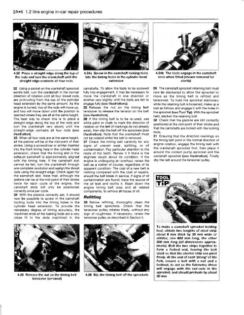
4.22 Place a straight edge along the top of<br />
the rods and turn the crankshaft until the<br />
straight edge contacts all four rods<br />
22 Using a socket on the crankshaft sprocket<br />
centre bolt, turn the crankshaft in the normal<br />
direction of rotation until all four dowel rods<br />
are protruding from the top of the cylinder<br />
head extension by the same amount. As the<br />
engine is turned, two of the rods will move up,<br />
and two will move down until the position is<br />
reached where they are all at the same height.<br />
The best way to check this is to place a<br />
straight-edge along the top of the rods and<br />
turn the crankshaft very slowly until the<br />
straight-edge contacts all four rods (see<br />
illustration).<br />
23 When all four rods are at the same height,<br />
all the pistons will be at the mid-point of their<br />
stroke. Using a screwdriver or similar inserted<br />
into the front timing hole in the cylinder head<br />
extension, check that the timing slot in the<br />
exhaust camshaft is approximately aligned<br />
with the timing hole. If the camshaft slot<br />
cannot be felt, turn the crankshaft through<br />
one complete revolution and realign the dowel<br />
rods using the straight-edge. Check again for<br />
the camshaft slot. Note that, although the<br />
pistons can be at the mid-point of their stroke<br />
twice for each cycle of the engine, the<br />
camshaft slots will only be positioned<br />
correctly once per cycle.<br />
24 With the pistons correctly set, it should<br />
now be possible to screw in the camshaft<br />
locking tools into the timing holes in the<br />
cylinder head extension. <strong>To</strong> provide the<br />
necessary degree of timing accuracy, the<br />
machined ends of the locking tools are a very<br />
close fit in the slots machined in the<br />
4.25 Release the nut on the timing belt<br />
tensioner (arrowed)<br />
4.24a Screw in the camshaft locking tools<br />
into the timing holes in the cylinder head<br />
extension<br />
camshafts. <strong>To</strong> allow the tools to be screwed<br />
fully into engagement, it may be necessary to<br />
move the crankshaft in one direction or<br />
another very slightly until the tools are felt to<br />
engage fully (see illustrations).<br />
25 Release the nut on the timing belt<br />
tensioner to release the tension on the belt<br />
(see illustration).<br />
26 If the timing belt is to be re-used, use<br />
white paint or chalk to mark the direction of<br />
rotation on the belt (if markings do not already<br />
exist), then slip the belt off the sprockets (see<br />
illustration). Note that the crankshaft must<br />
not be rotated whilst the belt is removed.<br />
27 Check the timing belt carefully for any<br />
signs of uneven wear, splitting, or oil<br />
contamination. Pay particular attention to the<br />
roots of the teeth. Renew it if there is the<br />
slightest doubt about its condition. If the<br />
engine is undergoing an overhaul, renew the<br />
belt as a matter of course, regardless of its<br />
apparent condition. The cost of a new belt is<br />
nothing compared with the cost of repairs,<br />
should the belt break in service. If signs of oil<br />
contamination are found, trace the source of<br />
the oil leak and rectify it. Wash down the<br />
engine timing belt area and all related<br />
components, to remove all traces of oil.<br />
Refitting<br />
28 Before refitting, thoroughly clean the<br />
timing belt sprockets. Check that the<br />
tensioner pulley rotates freely, without any<br />
sign of roughness. If necessary, renew the<br />
tensioner pulley as described in Section 5.<br />
4.26 Slip the timing belt off the sprockets<br />
4.24b The tools engage in the camshaft<br />
slots when fitted (shown removed for<br />
clarity)<br />
29 The camshaft sprocket retaining bolt must<br />
now be slackened to allow the sprocket to<br />
move as the timing belt is refitted and<br />
tensioned. <strong>To</strong> hold the sprocket stationary<br />
while the retaining bolt is loosened, make up a<br />
tool as follows and engage it with the holes in<br />
the sprocket (see <strong>To</strong>ol Tip). With the sprocket<br />
held, slacken the retaining bolt.<br />
30 Check that the pistons are still correctly<br />
positioned at the mid-point of their stroke and<br />
that the camshafts are locked with the locking<br />
tools.<br />
31 Ensuring that the direction markings on<br />
the timing belt point in the normal direction of<br />
engine rotation, engage the timing belt with<br />
the crankshaft sprocket first, then place it<br />
around the coolant pump sprocket and the<br />
camshaft sprocket (see illustration). Finally<br />
slip the belt around the tensioner pulley.<br />
TOOL<br />
<strong>To</strong> make a camshaft sprocket holding<br />
tool, obtain two lengths of steel strip<br />
about 6 mm thick by 30 mm wide or<br />
similar, one 600 mm long, the other<br />
200 mm long (all dimensions approximate).<br />
Bolt the two strips together to<br />
form a forked end, leaving the bolt<br />
slack so that the shorter strip can pivot<br />
freely. At the end of each 'prong' of the<br />
fork, secure a bolt with a nut and a<br />
locknut, to act as the fulcrums; these<br />
will engage with the cut-outs in the<br />
sprocket, and should protrude by about<br />
30 mm


