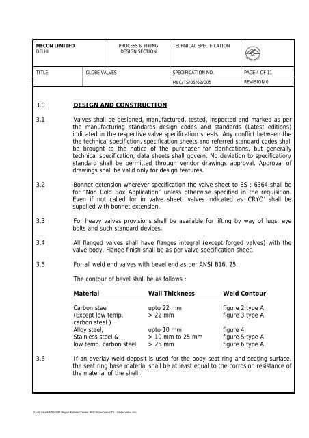
- Page 1 and 2:
GAIL (India) Limited TENDER DOCUMEN
- Page 3 and 4:
D:\old data\FATEH\IDPL_Dholpur\SCC\
- Page 5 and 6:
MECON LIMITED REGD. OFF: RANCHI (BI
- Page 7 and 8:
MECON LIMITED REGD. OFF : RANCHI (B
- Page 9 and 10:
MECON LIMITED REGD. OFF : RANCHI (B
- Page 11 and 12:
MECON LIMITED REGD. OFF : RANCHI (B
- Page 13 and 14:
MECON LIMITED REGD. OFF : RANCHI (B
- Page 15 and 16:
MECON LIMITED REGD. OFF : RANCHI (B
- Page 17 and 18:
MECON LIMITED REGD. OFF : RANCHI (B
- Page 19 and 20:
MECON LIMITED REGD. OFF : RANCHI (B
- Page 21 and 22:
MECON LIMITED REGD. OFF : RANCHI (B
- Page 23 and 24:
MECON LIMITED REGD. OFF : RANCHI (B
- Page 25 and 26:
MECON LIMITED REGD. OFF : RANCHI (B
- Page 27 and 28:
MECON LIMITED REGD. OFF : RANCHI (B
- Page 29 and 30:
MECON LIMITED REGD. OFF : RANCHI (B
- Page 31 and 32:
MECON LIMITED REGD. OFF : RANCHI (B
- Page 33 and 34:
MECON LIMITED REGD. OFF : RANCHI (B
- Page 35 and 36:
MECON LIMITED REGD. OFF : RANCHI (B
- Page 37 and 38:
MECON LIMITED REGD. OFF : RANCHI (B
- Page 39 and 40:
MECON LIMITED REGD. OFF : RANCHI (B
- Page 41 and 42:
MECON LIMITED REGD. OFF : RANCHI (B
- Page 43 and 44:
MECON LIMITED REGD. OFF : RANCHI (B
- Page 45 and 46:
MECON LIMITED REGD. OFF : RANCHI (B
- Page 47 and 48:
MECON LIMITED REGD. OFF : RANCHI (B
- Page 49 and 50:
MECON LIMITED REGD. OFF : RANCHI (B
- Page 51 and 52:
MECON LIMITED REGD. OFF : RANCHI (B
- Page 53 and 54:
MECON LIMITED REGD. OFF : RANCHI (B
- Page 55 and 56:
MECON LIMITED REGD. OFF : RANCHI (B
- Page 57:
MECON LIMITED REGD. OFF : RANCHI (B
- Page 61 and 62:
MECON LIMITED REGD. OFF: RANCHI (BI
- Page 63 and 64:
MECON LIMITED REGD. OFF : RANCHI (B
- Page 65 and 66:
MECON LIMITED REGD. OFF : RANCHI (B
- Page 67 and 68:
MECON LIMITED REGD. OFF : RANCHI (B
- Page 69 and 70:
MECON LIMITED REGD. OFF : RANCHI (B
- Page 71 and 72:
MECON LIMITED REGD. OFF : RANCHI (B
- Page 73 and 74:
MECON LIMITED REGD. OFF : RANCHI (B
- Page 75 and 76:
MECON LIMITED REGD. OFF : RANCHI (B
- Page 77 and 78:
MECON LIMITED REGD. OFF : RANCHI (B
- Page 79 and 80:
MECON LIMITED REGD. OFF : RANCHI (B
- Page 81 and 82:
Pipe Size, Out Side Diamter- Inches
- Page 83 and 84:
MECON LIMITED REGD. OFF : RANCHI (B
- Page 85 and 86:
MECON LIMITED REGD. OFF : RANCHI (B
- Page 87 and 88:
MECON LIMITED REGD. OFF : RANCHI (B
- Page 89 and 90:
MECON LIMITED REGD. OFF : RANCHI (B
- Page 91 and 92:
MECON LIMITED REGD. OFF : RANCHI (B
- Page 93 and 94:
MECON LIMITED REGD. OFF : RANCHI (B
- Page 95 and 96:
\\Akjha\work contrac\standard TS fo
- Page 97 and 98:
MECON LIMITED REGD. OFF : RANCHI (B
- Page 99 and 100:
MECON LIMITED REGD. OFF : RANCHI (B
- Page 101 and 102:
MECON LIMITED REGD. OFF : RANCHI (B
- Page 103 and 104:
MECON LIMITED REGD. OFF : RANCHI (B
- Page 105 and 106:
MECON LIMITED REGD. OFF : RANCHI (B
- Page 107 and 108:
MECON LIMITED REGD. OFF : RANCHI (B
- Page 109 and 110:
MECON LIMITED REGD. OFF : RANCHI (B
- Page 111:
MECON LIMITED REGD. OFF : RANCHI (B
- Page 120 and 121:
SPECIFICATION FOR HYDROSTATIC TESTI
- Page 122 and 123:
MECON LIMITED REGD. OFF : RANCHI (B
- Page 124 and 125:
MECON LIMITED REGD. OFF : RANCHI (B
- Page 126 and 127:
c:\fateh\standard\stad-eqp.wp NEW D
- Page 128 and 129:
MECON LIMITED REGD. OFF : RANCHI (B
- Page 130 and 131:
MECON LIMITED REGD. OFF : RANCHI (B
- Page 132 and 133:
MECON LIMITED REGD. OFF : RANCHI (B
- Page 134 and 135:
MECON LIMITED REGD. OFF : RANCHI (B
- Page 136 and 137:
MECON LIMITED REGD. OFF : RANCHI (B
- Page 138 and 139:
0 C C; \ts\Tender-A,4.doc. TABLE -
- Page 140 and 141:
0 C C; \ts\Tender-A,4.doc. TABLE -
- Page 143 and 144:
SPECIFICATION FOR MAJOR WATER CROSS
- Page 145 and 146:
MECON LIMITED REGD. OFF : RANCHI (B
- Page 147 and 148:
MECON LIMITED REGD. OFF : RANCHI (B
- Page 149 and 150:
MECON LIMITED REGD. OFF : RANCHI (B
- Page 151 and 152:
MECON LIMITED REGD. OFF : RANCHI (B
- Page 153 and 154:
MECON LIMITED REGD. OFF : RANCHI (B
- Page 155 and 156:
MECON LIMITED REGD. OFF : RANCHI (B
- Page 157 and 158:
MECON LIMITED REGD. OFF : RANCHI (B
- Page 159 and 160:
MECON LIMITED REGD. OFF: RANCHI (BI
- Page 161 and 162:
MECON LIMITED REGD. OFF : RANCHI (B
- Page 163 and 164:
MECON LIMITED REGD. OFF : RANCHI (B
- Page 165 and 166:
MECON LIMITED REGD. OFF : RANCHI (B
- Page 167 and 168:
MECON LIMITED REGD. OFF : RANCHI (B
- Page 176 and 177:
SPECIFICATION FOR PIPING FABRICATIO
- Page 178 and 179:
MECON LIMITED REGD. OFF: RANCHI (BI
- Page 180 and 181:
MECON LIMITED REGD. OFF: RANCHI (BI
- Page 182 and 183:
MECON LIMITED REGD. OFF: RANCHI (BI
- Page 184 and 185:
MECON LIMITED REGD. OFF: RANCHI (BI
- Page 186 and 187:
MECON LIMITED REGD. OFF: RANCHI (BI
- Page 188 and 189:
MECON LIMITED REGD. OFF: RANCHI (BI
- Page 190 and 191:
MECON LIMITED REGD. OFF: RANCHI (BI
- Page 192 and 193:
MECON LIMITED REGD. OFF: RANCHI (BI
- Page 194 and 195:
MECON LIMITED REGD. OFF: RANCHI (BI
- Page 196 and 197:
MECON LIMITED REGD. OFF: RANCHI (BI
- Page 198 and 199:
MECON LIMITED REGD. OFF: RANCHI (BI
- Page 200 and 201:
MECON LIMITED REGD. OFF: RANCHI (BI
- Page 202 and 203:
MECON LIMITED REGD. OFF: RANCHI (BI
- Page 204 and 205:
MECON LIMITED REGD. OFF: RANCHI (BI
- Page 206 and 207:
MECON LIMITED REGD. OFF: RANCHI (BI
- Page 208 and 209:
MECON LIMITED REGD. OFF: RANCHI (BI
- Page 210 and 211:
MECON LIMITED REGD. OFF: RANCHI (BI
- Page 212 and 213:
MECON LIMITED REGD. OFF: RANCHI (BI
- Page 214 and 215:
MECON LIMITED REGD. OFF: RANCHI (BI
- Page 216 and 217:
MECON LIMITED REGD. OFF: RANCHI (BI
- Page 218 and 219:
MECON LIMITED REGD. OFF: RANCHI (BI
- Page 220 and 221:
Pipe Size, Outside diameter Inches
- Page 222 and 223:
MECON LIMITED REGD. OFF: RANCHI (BI
- Page 224 and 225:
MECON LIMITED REGD. OFF: RANCHI (BI
- Page 226 and 227:
MECON LIMITED REGD. OFF: RANCHI (BI
- Page 228 and 229:
MECON LIMITED REGD. OFF: RANCHI (BI
- Page 230 and 231:
MECON LIMITED REGD. OFF: RANCHI (BI
- Page 232 and 233:
MECON LIMITED REGD. OFF: RANCHI (BI
- Page 234 and 235:
MECON LIMITED REGD. OFF: RANCHI (BI
- Page 236 and 237:
MECON LIMITED REGD. OFF: RANCHI (BI
- Page 238:
MECON LIMITED REGD. OFF: RANCHI (BI
- Page 278 and 279:
CONTENTS Sl. Description Page No. N
- Page 280 and 281:
1.0 GENERAL 1.1 These technical spe
- Page 282 and 283:
completion and testing on system ar
- Page 284 and 285:
5.1.2 Mill scale, rust, rust scale
- Page 286 and 287:
5.2.3 Maual or hand tool cleaning M
- Page 288 and 289:
c. Ingredients shall be kept proper
- Page 290 and 291:
the bottom. This work shall be done
- Page 292 and 293:
S. NO. DESCRIPTION 1. MANUAL OR HAN
- Page 294 and 295:
S. NO. DESCRIPTION 3. BLAST CLEANIN
- Page 296 and 297:
6.0 PAINT MATERIALS Paint manufactu
- Page 298 and 299:
PAINT MATERIALS TABLE NO.: 6.2FINIS
- Page 300 and 301:
Notes: 1. Covering capacity and DFT
- Page 302 and 303:
TABLE 7.1: PRE-ERECTION/ PRE-FABRIC
- Page 304 and 305:
NOTE 2 : FOR EXTENAL SURFACE OF RCC
- Page 306 and 307:
TABLE 10.0: FIELD PAINT SYSTEM FOR
- Page 308 and 309:
TABLE 12.0 : FIELD PAINT SYSTEM FOR
- Page 310:
TABLE 14.0 : PAINTING UNDER INSULAT
- Page 313 and 314:
17.0 STORAGE 17.1 All paints and pa
- Page 315 and 316:
. Intersection points & change of d
- Page 317 and 318:
20.3 Method of Camouflaging 20.3.1
- Page 319 and 320:
it would be in the interest of the
- Page 321 and 322:
24.5 Tests required for evaluation
- Page 323 and 324:
S. No. MANUFACTURER NAME LIST OF RE
- Page 325 and 326:
S. No. MANUFACTURER NAME LIST OF RE
- Page 327 and 328:
S. NO. LIST OF RECOMMENDED MANUFACT
- Page 329 and 330:
SPECIFICATION FOR REPAIR OF PIPELIN
- Page 331 and 332:
MECON LIMITED DELHI PROCESS & PIPIN
- Page 333 and 334:
SPECIFICATION FOR DOCUMENTATION FOR
- Page 335 and 336:
1.0 SCOPE 1.1 This specification co
- Page 337 and 338:
2.3 Monthly • Priced variations
- Page 339 and 340:
- Major water crossings - Waste dis
- Page 341 and 342:
- Location of further appurtenance
- Page 343 and 344:
Document2 SPECIFICATION FOR PIPELIN
- Page 345 and 346:
MECON LIMITED REGD. OFF : RANCHI (B
- Page 347:
MECON LIMITED REGD. OFF : RANCHI (B
- Page 355 and 356:
MECON LIMITED REGD. OFF: RANCHI (BI
- Page 357 and 358:
MECON LIMITED REGD. OFF: RANCHI (BI
- Page 359 and 360:
MECON LIMITED REGD. OFF: RANCHI (BI
- Page 361 and 362:
MECON LIMITED REGD. OFF: RANCHI (BI
- Page 363 and 364:
MECON LIMITED REGD. OFF: RANCHI (BI
- Page 365 and 366:
MECON LIMITED REGD. OFF: RANCHI (BI
- Page 367 and 368:
MECON LIMITED REGD. OFF : RANCHI (B
- Page 369 and 370:
MECON LIMITED REGD. OFF : RANCHI (B
- Page 371:
SPECIFICATION FOR VENTS, DRAINS AND
- Page 378 and 379:
MECON LIMITED REGD. OFF: RANCHI (BI
- Page 380 and 381:
MECON LIMITED REGD. OFF: RANCHI (BI
- Page 382 and 383:
1.0 SCOPE TABLE OF CONTENTS 2.0 COD
- Page 384 and 385:
The last letter indicates type of m
- Page 386 and 387:
10.0 GASKETS 10.1 Spiral wound meta
- Page 388:
13.7 Unless specified otherwise. Va
- Page 396 and 397:
D:\old data\FATEH\Aban Power\TS\Spe
- Page 398 and 399:
determination of surface profile -
- Page 400 and 401:
) Peel Strength shall be as follows
- Page 402 and 403:
accordance with ISO:8503-3 or ISO:8
- Page 404 and 405:
4.3 Application Procedure for Corro
- Page 406 and 407:
Company Representative reserves the
- Page 408 and 409:
SPECIFICATION FOR 3-LAYER POLYETHYL
- Page 410 and 411:
1.0 SCOPE This specification covers
- Page 412 and 413:
y. CSA Z245.20-98 : External Fusion
- Page 414 and 415:
which failed. If all tests pass, th
- Page 416 and 417:
5.3.3 Properties of Coating System
- Page 418 and 419:
health and safety sheets and manufa
- Page 420 and 421:
7.4.4 Chemical Pre-Treatment 7.4.4.
- Page 422 and 423:
specified temperature i.e. one at e
- Page 424 and 425:
• Any time when in COMPANY’s op
- Page 426 and 427:
8.6.4 After the de-ionised water wa
- Page 428 and 429:
8.13.4 The CONTRACTOR shall check t
- Page 430 and 431:
i. Electrostatic application of epo
- Page 432 and 433:
9.2.12 Failure to comply with any o
- Page 434 and 435:
area on the pipe shall show presenc
- Page 436 and 437:
10.10 Epoxy Layer Adhesive Test a.
- Page 438 and 439:
11.3 The CONTRACTOR shall load, unl
- Page 440 and 441:
• Damages caused to coating by ha
- Page 442 and 443:
14.6 The CONTRACTOR’s Quality sys
- Page 444 and 445:
Table - 1 Manufacturers Data on Coa
- Page 446 and 447:
MECON LIMITED Delhi PROCESS & PIPIN
- Page 448 and 449:
MECON LIMITED Delhi PROCESS & PIPIN
- Page 450 and 451:
MECON LIMITED Delhi PROCESS & PIPIN
- Page 453 and 454:
PROCESS & PIPING DESIGN SECTION MEC
- Page 455 and 456:
MECON LIMITED Delhi PROCESS & PIPIN
- Page 457 and 458:
MECON LIMITED Delhi PROCESS & PIPIN
- Page 459 and 460:
MECON LIMITED Delhi PROCESS & PIPIN
- Page 461 and 462:
MECON LIMITED Delhi PROCESS & PIPIN
- Page 463 and 464:
PROCESS & PIPING DESIGN SECTION MEC
- Page 465 and 466:
MECON LIMITED Delhi PROCESS & PIPIN
- Page 467 and 468:
MECON LIMITED Delhi PROCESS & PIPIN
- Page 469 and 470:
MECON LIMITED Delhi PROCESS & PIPIN
- Page 471 and 472:
MECON LIMITED Delhi PROCESS & PIPIN
- Page 473 and 474:
SPECIFICATION FOR PIPELINE PRE-COMM
- Page 475 and 476:
MECON LIMITED REGD. OFF : RANCHI (B
- Page 477 and 478:
MECON LIMITED REGD. OFF : RANCHI (B
- Page 479 and 480:
MECON LIMITED REGD. OFF : RANCHI (B
- Page 481 and 482:
MECON LIMITED REGD. OFF : RANCHI (B
- Page 483 and 484:
C O N T E N T S Clause No. Title Pa
- Page 485 and 486:
Above 250 & upto 500 - Deploy one q
- Page 487 and 488:
e. Fabricated steel structurals, pi
- Page 489 and 490:
4.0 DETAILS OF HSE MANAGEMENT SYSTE
- Page 491 and 492:
RELEVANT IS-CODES FOR PERSONNEL PRO
- Page 494 and 495:
2.0 MONTHLY CHECKLIST CUM COMPLIANC
- Page 496 and 497:
MONTHLY CHECKLIST CUM COMPLIANCE RE
- Page 498 and 499:
MONTHLY CHECKLIST CUM COMPLIANCE RE
- Page 500 and 501:
ANNEXURE-B Format-3 3.0 ACCIDENT RE
- Page 502 and 503:
5.0 MONTHLY Health, Safety & Enviro
- Page 504 and 505:
MECON LIMITED REGD. OFF : RANCHI (B
- Page 506 and 507:
MECON LIMITED REGD. OFF : RANCHI (B
- Page 508 and 509:
MECON LIMITED REGD. OFF : RANCHI (B
- Page 510 and 511:
MECON LIMITED REGD. OFF : RANCHI (B
- Page 512 and 513:
OBSERVATION OF QUALITY ASPECTS Job
- Page 514 and 515:
SPECIFICATION FOR CALIPER PIGGING S
- Page 516 and 517:
1.0 INTENT 2.0 OBJECTIVE SPECIFICAT
- Page 518 and 519:
6.0 GAUGE PIG RUN Contractor to car
- Page 520 and 521:
- Valves or any partially closed va
- Page 522 and 523:
geometry inspection to generate val
- Page 524 and 525:
PIPELINE DETAILS NOMINAL DIAMETER m
- Page 526 and 527:
CONTENTS Sl.No. Description Page No
- Page 528 and 529:
) SIS - 055900 : Pictorial surface
- Page 530 and 531:
Property Test Method Condition Requ
- Page 532 and 533:
35mm The sleeve shall be installed
- Page 534 and 535:
4.1 General a) The application proc
- Page 536 and 537:
4.3 Procedure a) The application pr
- Page 538 and 539:
5.2.3 All the coated joints shall b
- Page 540 and 541:
8.0 REPAIR OF PIPE COATING DEFECTS
- Page 542 and 543:
MECON LIMITED Delhi PROCESS & PIPIN
- Page 544 and 545:
MECON LIMITED Delhi PROCESS & PIPIN
- Page 546 and 547:
MECON LIMITED Delhi PROCESS & PIPIN
- Page 548 and 549:
MECON LIMITED Delhi PROCESS & PIPIN
- Page 550 and 551:
MECON LIMITED Delhi PROCESS & PIPIN
- Page 552 and 553:
MECON LIMITED Delhi PROCESS & PIPIN
- Page 554 and 555:
MECON LIMITED REGD. OFF RANCHI PROC
- Page 556 and 557:
MECON LIMITED REGD. OFF RANCHI PROC
- Page 558 and 559:
MECON LIMITED REGD. OFF RANCHI PROC
- Page 560 and 561:
MECON LIMITED REGD. OFF RANCHI PROC
- Page 562 and 563:
D:\TS\Lond Redius Bends - 015-R1.do
- Page 564 and 565:
MECON LIMITED DELHI D:\TS\Lond Redi
- Page 566 and 567:
MECON LIMITED DELHI D:\TS\Lond Redi
- Page 568 and 569:
MECON LIMITED DELHI D:\TS\Lond Redi
- Page 570 and 571:
MECON LIMITED DELHI D:\TS\Lond Redi
- Page 572 and 573:
MECON LIMITED REGD. OFF RANCHI PROC
- Page 574 and 575:
MECON LIMITED REGD. OFF RANCHI PROC
- Page 576 and 577:
MECON LIMITED REGD. OFF RANCHI PROC
- Page 578 and 579:
MECON LIMITED REGD. OFF RANCHI PROC
- Page 580 and 581:
MECON LIMITED REGD. OFF RANCHI PROC
- Page 582 and 583:
D:\TS\Specification for Split Tee (
- Page 584 and 585:
MECON LIMITED REGD. OFF RANCHI PROC
- Page 586 and 587:
MECON LIMITED REGD. OFF RANCHI PROC
- Page 588 and 589:
MECON LIMITED REGD. OFF RANCHI PROC
- Page 590 and 591:
MECON LIMITED REGD. OFF RANCHI PROC
- Page 592 and 593:
D:\TS\PSV - TS - 056 (R-1).doc PROC
- Page 594 and 595:
MECON LIMITED Delhi PROCESS & PIPIN
- Page 596 and 597:
MECON LIMITED Delhi PROCESS & PIPIN
- Page 598 and 599:
MECON LIMITED Delhi PROCESS & PIPIN
- Page 600 and 601:
MECON LIMITED Delhi PROCESS & PIPIN
- Page 602 and 603:
D:\TS\Cartridge Filter - 017 - TS.d
- Page 604 and 605:
MECON LIMITED REGD. OFF RANCHI PROC
- Page 606 and 607:
MECON LIMITED REGD. OFF RANCHI PROC
- Page 608 and 609:
MECON LIMITED REGD. OFF RANCHI PROC
- Page 610 and 611:
MECON LIMITED REGD. OFF RANCHI PROC
- Page 612 and 613:
MECON LIMITED REGD. OFF RANCHI PROC
- Page 614 and 615:
MECON LIMITED REGD. OFF RANCHI PROC
- Page 616 and 617: MECON LIMITED REGD. OFF RANCHI PROC
- Page 618 and 619: MECON LIMITED REGD. OFF RANCHI PROC
- Page 620 and 621: MECON LIMITED REGD. OFF RANCHI PROC
- Page 622 and 623: MECON LIMITED REGD. OFF RANCHI PROC
- Page 624 and 625: MECON LIMITED REGD. OFF RANCHI PROC
- Page 626 and 627: MECON LIMITED REGD. OFF RANCHI PROC
- Page 628 and 629: D:\Technical Specifications & Stand
- Page 630 and 631: MECON LIMITED REGD. OFF RANCHI PROC
- Page 632 and 633: MECON LIMITED REGD. OFF RANCHI PROC
- Page 634 and 635: MECON LIMITED REGD. OFF RANCHI PROC
- Page 636 and 637: MECON LIMITED REGD. OFF RANCHI PROC
- Page 638 and 639: MECON LIMITED REGD. OFF RANCHI PROC
- Page 640 and 641: MECON LIMITED Delhi PROCESS & PIPIN
- Page 642 and 643: MECON LIMITED Delhi PROCESS & PIPIN
- Page 644 and 645: MECON LIMITED Delhi PROCESS & PIPIN
- Page 646 and 647: MECON LIMITED Delhi PROCESS & PIPIN
- Page 648 and 649: MECON LIMITED Delhi PROCESS & PIPIN
- Page 650 and 651: MECON LIMITED Delhi PROCESS & PIPIN
- Page 652 and 653: MECON LIMITED Delhi PROCESS & PIPIN
- Page 654 and 655: MECON LIMITED Delhi PROCESS & PIPIN
- Page 656 and 657: MECON LIMITED Delhi PROCESS & PIPIN
- Page 658 and 659: MECON LIMITED Delhi PROCESS & PIPIN
- Page 660 and 661: MECON LIMITED Delhi PROCESS & PIPIN
- Page 662 and 663: PROCESS & PIPING DESIGN SECTION MEC
- Page 664 and 665: MECON LIMITED DELHI D:\old data\FAT
- Page 668 and 669: MECON LIMITED DELHI D:\old data\FAT
- Page 670 and 671: MECON LIMITED DELHI D:\old data\FAT
- Page 672 and 673: MECON LIMITED DELHI D:\old data\FAT
- Page 674 and 675: PROCESS & PIPING DESIGN SECTION MEC
- Page 676 and 677: MECON LIMITED Delhi PROCESS & PIPIN
- Page 678 and 679: MECON LIMITED Delhi PROCESS & PIPIN
- Page 680 and 681: MECON LIMITED Delhi PROCESS & PIPIN
- Page 682 and 683: MECON LIMITED Delhi PROCESS & PIPIN
- Page 684 and 685: MECON LIMITED Delhi PROCESS & PIPIN
- Page 686 and 687: MECON LIMITED Delhi PROCESS & PIPIN
- Page 688 and 689: MECON LIMITED Delhi PROCESS & PIPIN
- Page 690 and 691: MECON LIMITED Delhi PROCESS & PIPIN
- Page 692 and 693: MECON LIMITED Delhi PROCESS & PIPIN
- Page 694 and 695: MECON LIMITED Delhi PROCESS & PIPIN
- Page 696 and 697: MECON LIMITED Delhi PROCESS & PIPIN
- Page 698 and 699: MECON LIMITED Delhi PROCESS & PIPIN
- Page 700 and 701: MECON LIMITED Delhi PROCESS & PIPIN
- Page 702 and 703: MECON LIMITED Delhi PROCESS & PIPIN
- Page 704 and 705: MECON LIMITED Delhi PROCESS & PIPIN
- Page 706 and 707: MECON LIMITED Delhi PROCESS & PIPIN
- Page 708 and 709: MECON LIMITED Delhi PROCESS & PIPIN
- Page 710 and 711: MECON LIMITED Delhi PROCESS & PIPIN
- Page 712 and 713: MECON LIMITED Delhi PROCESS & PIPIN
- Page 714 and 715: MECON LIMITED Delhi PROCESS & PIPIN
- Page 716 and 717:
MECON LIMITED Delhi PROCESS & PIPIN
- Page 718 and 719:
MECON LIMITED Delhi PROCESS & PIPIN
- Page 720 and 721:
MECON LIMITED Delhi PROCESS & PIPIN
- Page 722 and 723:
C O N T E N T S Sl.No. Description
- Page 724 and 725:
e measured. Hence the depth of meas
- Page 726 and 727:
6.7 Graphical representation of exi
- Page 728 and 729:
GAIL (India) Limited TECHNICAL SPEC
- Page 730 and 731:
1.0 SCOPE Cathodic Protection Power
- Page 732 and 733:
limit feature shall be provided in
- Page 734 and 735:
e) Pipeline under protected f) Auto
- Page 736 and 737:
- Dimensional checking - Proper mou


