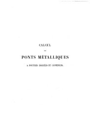
- Page 1 and 2:
PRÁCTICA USUAL DE LOS CÁLCULOS DE
- Page 3 and 4:
-6- práctica de los principios que
- Page 5 and 6:
PARTE PRIMERA. NOCIONES DE RESISTEN
- Page 7 and 8:
-J1- l .diculares al mismo, ó para
- Page 9 and 10:
-13- extensión (1). Asi, si vamos
- Page 11 and 12:
-15 - valíéndose de las tablas qu
- Page 13 and 14:
. -17- sarios cuanto más compleja
- Page 15 and 16:
-19 ~ obras de Constp.lcción ó Me
- Page 17 and 18:
-21- un aumento creciente con la lu
- Page 19 and 20:
-23 - Muchas sonta~bién , las fór
- Page 21 and 22:
-25.-. Estas fórmulas se mencionan
- Page 23 and 24:
. --". 27 - bremos eliminado r, y c
- Page 25 and 26:
-29- tados no difieren sensiblement
- Page 27 and 28:
1 . Ro 1 R Valores de li Valores de
- Page 29 and 30:
- 33..,..... no influye prácticame
- Page 31 and 32:
, to - 35- los trozos de viga, por
- Page 33 and 34:
. -37- l.a lJados lospesos que obra
- Page 35 and 36:
-39 - " Del mismo modo proced'eriam
- Page 37 and 38:
dad de los momentos FXd- -..41- ~ X
- Page 39 and 40:
, -043..- metálicos, bastaría sum
- Page 41 and 42:
- 45 .- ellosdebe reducirse áUll p
- Page 43 and 44:
- 47-- ciones de los apoyos 'son X
- Page 45 and 46:
-49 - 2.° Que E'decrece proporcion
- Page 47 and 48:
,.51- btengan, porque, como en el c
- Page 49 and 50:
-53- En el casodela figura 12, el m
- Page 51 and 52:
-'55- rros de ángulo y chapas hori
- Page 53 and 54:
- 57- Del mismo modo se aplica el c
- Page 55 and 56:
- 59 -;- Ifj~ementeti razón de 200
- Page 57 and 58:
- 61- De las cargas móviles, se co
- Page 59 and 60:
, - 63- Para obtener la sección ac
- Page 61 and 62:
-{)5 - En el cuadro núm. 1 vemos q
- Page 63 and 64:
de donde Esta sección deberíamos
- Page 65 and 66:
- 69 .-:. -puntos a y b, antes bien
- Page 67 and 68:
la recta N L, cuyas ordenadas dan
- Page 69 and 70:
...,- 13 ...,- El empotramiento per
- Page 71 and 72:
-.75- Si despreciamos el momento de
- Page 73 and 74:
CAPÍTULO - III- REPARTICiÓN DE LA
- Page 75 and 76:
- 79 ,.--, hallan eIl las mismas co
- Page 77 and 78:
,-- 81 - en la cual M es el momento
- Page 79 and 80:
~83- fuerzas X YX' aplicadas á los
- Page 81 and 82:
- 85- El máximo de R se verifica e
- Page 83 and 84:
- 87- Se ha prescindido de la super
- Page 85 and 86:
.CAPÍTULO IV. PRINCIPIOS DE LA EST
- Page 87 and 88:
- 91- En la figura (B)se han repres
- Page 89 and 90:
- 93- gulo dan una resultante igual
- Page 91 and 92:
- 95- su intersección se trazará
- Page 93 and 94:
- 97- figura (A), y, por lo tanto,
- Page 95 and 96:
- 99,- de Estática gráfica; pero,
- Page 97 and 98:
- 101 - del nudo a hacia la derecha
- Page 99 and 100:
- 103 - mosal b, encontrariamos tre
- Page 101 and 102:
- ,105- Con' esto conocemos todas l
- Page 103 and 104:
- 107 - gravedad sean conocidos, y
- Page 105 and 106:
P A,RTE SEGUNDA. OAPÍTULO I. FÓRM
- Page 107 and 108:
y El mismo triángulo da l 2 - 111
- Page 109 and 110:
- 113- es decir, tomar en la vertic
- Page 111 and 112:
, - 115 - iJ'ucciones de mamposter
- Page 113 and 114:
- 117 - Si se sustituyen estos valo
- Page 115 and 116:
- 119 - clave reemplazando ,en las
- Page 117 and 118:
- 121 - DesnQyers da, para este cas
- Page 119 and 120:
- 123 - formarse el cuadro núm. 4,
- Page 121 and 122:
Arcos escarzanos - 125 -"- E= VI [0
- Page 123 and 124:
- 127 - clave de la bóveda, y se c
- Page 125 and 126:
Altura Luces I Epoca de Espesor Esp
- Page 127 and 128:
Altura Luces Espesor I ' Epoca de E
- Page 129 and 130:
. hacia el exterior alrededor de lo
- Page 131 and 132:
- 135'- á indicar lo esencial de e
- Page 133 and 134:
- 137 - dera una bóveda estable -'
- Page 135 and 136:
- 139 - de rotura. En muchos casos
- Page 137 and 138:
e 61. CAPÍTULO III. TEORíA DE LA
- Page 139 and 140:
- 143- P1 + P2 + Pa, y, por lo tant
- Page 141 and 142:
- 145 - probación de esta tercera
- Page 143 and 144:
' tuirá como acabamos de indicar p
- Page 145 and 146:
- 149 - de b un cuadrilátero, y se
- Page 147 and 148:
, el empuje en la clave, hemos part
- Page 149 and 150:
- 153 - partir de la horizontal a q
- Page 151 and 152:
- 155 - á nq, ambas reacciones deb
- Page 153 and 154:
- 157 - acabamos de indicar se corr
- Page 155 and 156:
- 159 - para trazar la curva de pre
- Page 157 and 158:
- 161 - 75. COMPROBACIÓN POR 'EL M
- Page 159 and 160:
-, J63 - Q = P d = 79..000X 3,50 =
- Page 161 and 162:
- 165 - caso, nos ponemos así en l
- Page 163 and 164:
~ .167 - método del coeficiente de
- Page 165 and 166:
I ~ "C ¡:j ~ "C .... o .m ~ ~ "C..
- Page 167 and 168:
'" '" ~ÁREAS ~Angulos Componen- Di
- Page 169 and 170:
-' 173 - remos por 'determinar las
- Page 171 and 172:
y - 175 =- 377.956;, 1ft = ' == 210
- Page 173 and 174:
-1>:) Q;) 'd 'c:I .G) 'd . o "" iD'
- Page 175 and 176:
_. 179 - cuentaantesdedecidirse:á
- Page 177 and 178:
Número Número Long'itud Presiones
- Page 179 and 180:
- 183 - prisma se mantendrá en equ
- Page 181 and 182:
- 185 - ó lo que es lo mismo el á
- Page 183 and 184:
- 11'87 :... especialmente en las a
- Page 185 and 186:
- 189 - 85. MUROS CON EL PARAMENTO
- Page 187 and 188:
- 191 - y el peso, admitiendo.,quee
- Page 189 and 190:
, - 193 - Así, si el ancho de la v
- Page 191 and 192:
-' 195- .estabilidad del muro de' 5
- Page 193 and 194:
y la presión máxima - 197 - 2 X 1
- Page 195 and 196:
PARTE TERCERA. PUENTES METÁLICOS D
- Page 197 and 198:
-201 - que se transmitirá á dos p
- Page 199 and 200: - 203 - 93. DETERMINACIÓN DE LAS C
- Page 201 and 202: . - 205 - para carretera. Esta cifr
- Page 203 and 204: - 201- No nos es posfble entrar en
- Page 205 and 206: " frecuente -.209.- Pa,ra las longi
- Page 207 and 208: -211 - , El trén co?tante qU'e'Ín
- Page 209 and 210: -213 - Se han deducido directamente
- Page 211 and 212: , e -215'- , Lospesosconsig~ados en
- Page 213 and 214: LUCES. CARGAS " CARGAS LUCES. LUCES
- Page 215 and 216: - 219 - , experimentos de Deslandre
- Page 217 and 218: - 221 -'- puesto que el resultado h
- Page 219 and 220: . - 223 -:- Supongamos que el piso
- Page 221 and 222: I - 225- Cuadro para la reducción
- Page 223 and 224: -227- roer lugar el caso más senci
- Page 225 and 226: , - 229 --- unidos al alma y aument
- Page 227 and 228: . . OAPÍTULO III. CÁLCULO DE LAS
- Page 229 and 230: ~I~ Fij 88 f :te Chapado JOmm~elllo
- Page 231 and 232: -235- eje h.orizontal y paralelo al
- Page 233 and 234: -237- Dada la simetría de la curva
- Page 235 and 236: - 239 - Pero así no tenemos en cue
- Page 237 and 238: - 241 - el trabajo real del hierro
- Page 239 and 240: OAPÍTULO IV. VIGAS DE CELOsíA ORD
- Page 241 and 242: -245- hipótesis que sirvió de bas
- Page 243 and 244: - 247 ~ Debemos observar, sin embar
- Page 245 and 246: - 249 - del apoyo se hallará toman
- Page 247 and 248: - 251 - cede, la luz de los larguer
- Page 249: - 253 - admitido el ancho mínimo p
- Page 253 and 254: apoyo de la derecha, de modo que e2
- Page 255 and 256: .. . . - 259 ~- En la zona 3.a redu
- Page 257 and 258: - 261 - de detalle, y podremos, por
- Page 259 and 260: ~ 263~ " Alma de 10 mm. á 77,88 po
- Page 261 and 262: -265- y el trabajo efectivo del met
- Page 263 and 264: - 267,- La mínima dimensión de l~
- Page 265 and 266: - 269 - menor dimensión de la secc
- Page 267 and 268: ~ 271 ;. 'l.° El sistema de trián
- Page 269 and 270: . -273- sistema simple que sirve de
- Page 271 and 272: - 275 - como centro de momentos el
- Page 273 and 274: - 277 - , 130. TENSIONES ,MÁXIMA y
- Page 275 and 276: - 279 - 131. SISTEMAS DE GRANDES MA
- Page 277 and 278: - 281 - Otra de las vigas de frecue
- Page 279 and 280: OAPÍTULO VI. VIGA RECTA DE MONTANT
- Page 281 and 282: -285- siendo lla luz. El momento de
- Page 283 and 284: . Tendremos la ecuación - 287 - 3
- Page 285 and 286: -289- - 'Esta misma dificultad se e
- Page 287 and 288: mw IJ máx - Te 6P + 2 - CoS!:l. 5
- Page 289 and 290: de. donde se deduce luego - 293 - d
- Page 291 and 292: de donde Luego 5. -. 1 .. -,-.295"-
- Page 293 and 294: -297 .~ fi'fontante V3.:.t~ós valo
- Page 295 and 296: - 299 - sometidos á tensión, pues
- Page 297 and 298: ~ 301 ; El peso permRnente, por met
- Page 299 and 300: - 303 - observando que el primero e
- Page 301 and 302:
. de donde resulta - 305 - maa; -,-
- Page 303 and 304:
y . ó' La ecuaCl n que det ermma v
- Page 305 and 306:
Luego - 309 ...,- v¡¡máx = 1)1/'
- Page 308 and 309:
Dmá:c- ~4.470 i - D má:c 2 - 51.2
- Page 310 and 311:
, - 314 - las secciones prácticas,
- Page 312 and 313:
. -316 ~. . 'Hemos dicho que el esf
- Page 314 and 315:
-318 - Finalmente,. 84 vendrá dada
- Page 316 and 317:
-320 - Admitiendo un trabajo de 8 k
- Page 318 and 319:
- 322 - '- montantes corresponden
- Page 320 and 321:
-324 --- manente en partes iguales
- Page 322 and 323:
Fácilmente veremos que - 326 --..
- Page 324 and 325:
-328- Teniepdo presente que esta ca
- Page 326 and 327:
- 330 - y escribiendo la ecuación
- Page 328 and 329:
-332~ Para determinar el debido á'
- Page 330 and 331:
~ 334~' Y sumando los esfuerzos deb
- Page 332 and 333:
, 336 --- ~ : En el cuadro siguient
- Page 334 and 335:
- 338 - 149. CÁLCULODEL DIAGRAMA(b
- Page 336 and 337:
. - 340 - 150. CÁLCULODE LOS MONTA
- Page 338 and 339:
- 342 -'- En el montante extremo ob
- Page 340 and 341:
" at' Se deduce de aqui Y, finalmen
- Page 342 and 343:
- 346 - La ecuación que determina
- Page 344 and 345:
de donde resulta Por lo tanto, -348
- Page 346 and 347:
Esfuerzos y secciones teóricas de
- Page 348 and 349:
OAPÍTULO VIII. VIGA DE MONTANTES Y
- Page 350 and 351:
~354- ocup~~nuna posición simétri
- Page 352 and 353:
-356- altura de la viga de 4 m., ig
- Page 354 and 355:
- 358 -' S2 X 4 + 30.120 X 8 - 3.76
- Page 356 and 357:
- 360 - pondiente á dicha carga, q
- Page 358 and 359:
1 4 [ ~"362 - 14 " ] 6.200 + 20 (7.
- Page 360 and 361:
- -364 - y 1)táX se obtendrá por
- Page 362 and 363:
1)61Jiá{J) se deducirá de la ecua
- Page 364 and 365:
nmá:JJ- V mín 4 10.,735X 1,41 = 1
- Page 366 and 367:
- 370- 158. DIAGRAMA(b) y VÍGA DEF
- Page 368 and 369:
- 372 - ',1 razón de su simetría
- Page 370 and 371:
OAPÍTULO IX. VIGAS PARABÓLlCAS. 1
- Page 372 and 373:
, - 376- de la compresión de la ca
- Page 374 and 375:
-378 ''-.-' x:=. i v. = 4ft. l2 x=
- Page 376 and 377:
- 380 - de las que descienden de iz
- Page 378 and 379:
, ~382- , ' lanca O' P' - Jn2 y O'
- Page 380 and 381:
- 384 -- ciales. Habremos cTeelegir
- Page 382 and 383:
- 386 - EIt virtud de la simetría
- Page 384 and 385:
luego -3'88 '~ 5 I ~ 96.500 X 252 =
- Page 386 and 387:
~ 390 ; las distancias al apoyo de
- Page 388 and 389:
de donde se ~educe l4 = El valor de
- Page 390 and 391:
-394- Haciendo las sustituciones, y
- Page 392 and 393:
-:-. 396 - Calcularemos ahora, D/n
- Page 394 and 395:
- 398 ~ y la inferior de cada monta
- Page 396 and 397:
de donde se deduce Vl&mín = - -400
- Page 398 and 399:
-402- parciales más desfavorables,
- Page 400 and 401:
OAPÍTULO x. APLICACiÓN DE LOS PRO
- Page 402 and 403:
. en una misma vertical, como se ve
- Page 404 and 405:
-408- última fuerza empuja á la a
- Page 406 and 407:
- 410- sujetas.sóloá tensiones y
- Page 408 and 409:
- 412 - Hé aquí cómo pueden disp
- Page 410 and 411:
- 414 - Los' triángulos rectángul
- Page 412 and 413:
- 416 - 169. CÁLCULODE LAS DIAGONA
- Page 414 and 415:
- 418 - de '1/2una par-alela á la
- Page 416 and 417:
PARTE OUARTA. VIGAS DE VARIOS TRAMO
- Page 418 and 419:
-423- por metro lineal uniformement
- Page 420 and 421:
-425- cer el signo del momento flec
- Page 422 and 423:
- 427 - Encontramos así el valor d
- Page 424 and 425:
- 429- eje paralelo al de su posici
- Page 426 and 427:
Pk lk Xa; = 2 - 431 - j}fk - Mk - 1
- Page 428 and 429:
'-4~3- can-las secciones de las bar
- Page 430 and 431:
,OA.PÍTULO II. VIGAS DE DOS TRAMOS
- Page 432 and 433:
~437 ~. -._Bajoesta forma se observ
- Page 434 and 435:
-439- 181. REACCIONES DE LOSAPoyos.
- Page 436 and 437:
-:-441- El valor de P en las fórmu
- Page 438 and 439:
-443- que será igual á la corresp
- Page 440 and 441:
~,445 ,~ M sera nulo para x = O, Y
- Page 442 and 443:
- 447 - 186. DISTRIBUCIÓN DE LAS C
- Page 444 and 445:
- 449'--' La reacción Ri del apoyo
- Page 446 and 447:
-451>- ,;Se determinárá la recta
- Page 448 and 449:
.;;;..-453 ~ 188. ."CILCULO DE LAS
- Page 450 and 451:
OAPÍTULO III. VIGAS DE TRES TRAMOS
- Page 452 and 453:
---,.4.,57. - () - 2 a (1+ v~) " MI
- Page 454 and 455:
-"'- 459 - Según eso, la carga cor
- Page 456 and 457:
- 461 ""'- ", 2.ah'@1ótesis.~Hacie
- Page 458 and 459:
-'463'''- Halia,remos los puntos en
- Page 460 and 461:
...:- 465 - Ma; = - 733.932+3.7202X
- Page 462 and 463:
- 467- Te
- Page 464 and 465:
TRAMOS. l." t",mo.. . . . . ¡ I Hi
- Page 466 and 467:
- 471-- El diagrama de la distribuc
- Page 468 and 469:
-=- 473 - 2.° tranw.-Lafórmula [6
- Page 470 and 471:
j Hipótesis Esfuerzo Esfuerzo - Va
- Page 472 and 473:
-477- y 9.a,. y finalmente, la 9.a
- Page 474 and 475:
OAPÍTULO IV. VIGAS DE CUATRO, CING
- Page 476 and 477:
- 481 - Si dividimos por 1 cada una
- Page 478 and 479:
- 483 - Si se quieren dibujar las r
- Page 480 and 481:
M1= - 485- Resolviendo este sistema
- Page 482 and 483:
-487- sobrecargas que hay necesidad
- Page 484 and 485:
- 489 - de fábrica, y entre 1 y 2
- Page 486 and 487:
-. 491 ~ Por ejemplo, si el desagü
- Page 488 and 489:
- 493 - bosque representan un gasto
- Page 490 and 491:
-495- cuatro tramos hayan de. ser i
- Page 492 and 493:
-497- Se emplearon mucho hace algun
- Page 494 and 495:
-499- Es imposible evitar en los tr
- Page 496:
...c- 501 - La fijación del límit
- Page 500 and 501:
n-
- Page 502 and 503:
. - 507 - 1 n n2 n 3 V; V; log. n n
- Page 504 and 505:
n n2 191 36481 192 36864 193 37249
- Page 506 and 507:
- - 511 - I I n n'1. n3 \/; Vn lag.
- Page 508 and 509:
- n n2 n3 391 152881 59776471 392 1
- Page 510 and 511:
- - 515 - ~Vn 1 n n2 n3 log. n 'iCn
- Page 512 and 513:
c, - - 517 - 1 n n2 n3 v; Vn log. n
- Page 514 and 515:
- - 519- n'l. n3 V; Vn log. n n n'7
- Page 516 and 517:
n - 521 - n2 n3 V; 3;- I 1 2 \' n l
- Page 518 and 519:
- -523- 1 n n2 n3 Vn Vn log. n 7t:n
- Page 520 and 521:
- 525- 1 n n2 n3 \l'n Vn log. n 7tn
- Page 522 and 523:
Grados. o 1 2 3 4 5 6 7 8 9 10 11 1
- Page 524 and 525:
Grados. - o 12 3 4 5 6 7 8 9 10 11
- Page 526 and 527:
- 531 - USO DE ESTAS TABLAS.-El uso
- Page 528 and 529:
Pesos por metro lineal, en kilogram
- Page 530 and 531:
-535- APÉNDICE NÚJ\if. 5. Tabla d
- Page 532 and 533:
Las fórmulas son: I ' - = 0,000.03
- Page 534 and 535:
ÍNDICE. PRÓLOGO.~-.... . ... . .
- Page 536 and 537:
541 - 44. Ap1i~ación de la composi
- Page 538 and 539:
- 543- PARTE TERCERA. PUENTES METÁ
- Page 540 and 541:
- 545 -=-- 138. Puente de 35 m. de
- Page 542 and 543:
, 217. .: 547 -:- CAPÍTULO rIT.-Vi
- Page 544 and 545:
PÁGINA lJNEA. DICE, DEBE DECIR. 37
- Page 546 and 547:
V MUó de R1. . Y J'~ ----- ~ ~ i ;
- Page 548 and 549:
I lb-1-- ' "- I "- I . i"' ! '" , ,
- Page 550 and 551:
--+--fJ2T>O //;:-/ -~_'i/~- // _.-'
- Page 552:
i I r ~ \ \~ I '-, \ ! \ c:-) O S '