Rexroth IndraDrive C Drive Controllers HCS02.1 ... - Bosch Rexroth
Rexroth IndraDrive C Drive Controllers HCS02.1 ... - Bosch Rexroth
Rexroth IndraDrive C Drive Controllers HCS02.1 ... - Bosch Rexroth

You also want an ePaper? Increase the reach of your titles
YUMPU automatically turns print PDFs into web optimized ePapers that Google loves.
6-28 Mounting and Installation <strong>Rexroth</strong> <strong>Indra<strong>Drive</strong></strong><br />
Arranging the Components in<br />
the Control Cabinet<br />
Cable Routing of the<br />
Interference-Free Lines to the<br />
Mains Connection<br />
Routing and Connecting a<br />
Neutral Conductor (N)<br />
Connecting Motor Blowers<br />
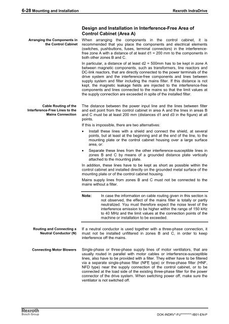
Design and Installation in Interference-Free Area of<br />
Control Cabinet (Area A)<br />
When arranging the components in the control cabinet, it is<br />
recommended that you place the components and electrical elements<br />
(switches, pushbuttons, fuses, terminal connectors) in the interferencefree<br />
zone A with a distance of at least d1 = 200 mm to the components in<br />
both other zones B and C.<br />
In particular, a distance of at least d2 = 500mm has to be kept in zone A<br />
between magnetic components, such as transformers, line reactors and<br />
DC-link reactors, that are directly connected to the power terminals of the<br />
drive system and the interference-free components and lines between<br />
supply system and filter including the mains filter. If this distance is not<br />
kept, the magnetic leakage fields are injected to the interference-free<br />
components and lines connected to the mains so that the limit values at<br />
the supply connection are exceeded in spite of the installed filter.<br />
The distance between the power input line and the lines between filter<br />
and exit point from the control cabinet in area A and the lines in areas B<br />
and C must be at least 200 mm (distances d1 and d3 in the figure) at all<br />
points.<br />
If this is impossible, there are two alternatives:<br />
• Install these lines with a shield and connect the shield, at several<br />
points, but at least at the beginning and at the end of the line, to the<br />
mounting plate or the control cabinet housing over a large surface<br />
area, or:<br />
• Separate these lines from the other interference-susceptible lines in<br />
zones B and C by means of a grounded distance plate vertically<br />
attached to the mounting plate.<br />
In addition, these lines have to be kept as short as possible within the<br />
control cabinet and installed directly on the grounded metal surface of the<br />
mounting plate or of the control cabinet housing.<br />
Mains supply lines from zones B and C must not be connected to the<br />
mains without a filter.<br />
Note: In case the information on cable routing given in this section is<br />
not observed, the effect of the mains filter is totally or partly<br />
neutralized. You must therefore expect the noise level of the<br />
interference emission to be higher within the range of 150 kHz<br />
to 40 MHz and the limit values at the connection points of the<br />
machine or installation to be exceeded.<br />
If a neutral conductor is used together with a three-phase connection, it<br />
must not be installed unfiltered in zones B and C, in order to keep<br />
interference off the mains.<br />
Single-phase or three-phase supply lines of motor ventilators, that are<br />
usually routed in parallel with motor cables or interference-susceptible<br />
lines, also have to be provided with a filter. They either have to be filtered<br />
via a separate single-phase filter (NFE type) or three-phase filter (HNF,<br />
NFD type) near the supply connection of the control cabinet, or to be<br />
connected at the load side of the existing three-phase filter for the power<br />
connector of the drive system. When switching power off, make sure the<br />
ventilator is not switched off.<br />
DOK-INDRV*-FU*********-IB01-EN-P