Rexroth IndraDrive C Drive Controllers HCS02.1 ... - Bosch Rexroth
Rexroth IndraDrive C Drive Controllers HCS02.1 ... - Bosch Rexroth
Rexroth IndraDrive C Drive Controllers HCS02.1 ... - Bosch Rexroth

Create successful ePaper yourself
Turn your PDF publications into a flip-book with our unique Google optimized e-Paper software.
7-132 Commissioning and Parameterization <strong>Rexroth</strong> <strong>Indra<strong>Drive</strong></strong><br />
position control loop<br />
velocity control loop<br />
S-0-0348<br />
S-0-0124<br />
S-0-0155<br />
P-0-1126<br />
current control loop<br />
P-0-0040<br />
P-0-0180<br />
current<br />
loop<br />
J,t<br />
1/P-0-0051<br />
filter cascade<br />
(N = 8)<br />
velocity<br />
loop<br />
F8079<br />
S-0-0032,<br />
bit 3 posit.<br />
loop<br />
PWM<br />
IPO<br />
Performance (Controller Cycle<br />
Times)<br />
-<br />
-<br />
-<br />
P-0-0001 S-0-0380<br />
S-0-0106<br />
S-0-0107<br />
S-0-0109<br />
S-0-0110<br />
P-0-0001<br />
P-0-0640<br />
S-0-0111<br />
P-0-0109<br />
S-0-0092<br />
S-0-0082<br />
S-0-0083<br />
P-0-1125 P-0-0004 P-0-1120 S-0-0100<br />
P-0-1121 S-0-0101<br />
P-0-1122<br />
P-0-1123<br />
S-0-0091<br />
S-0-0104<br />
S-0-0037<br />
S-0-0081<br />
P-0-0043<br />
act. current<br />
vact_motor<br />
actual velocity<br />
vact_ext. encoder<br />
P-0-1119<br />
actual<br />
position<br />
S-0-0051<br />
S-0-0053<br />
sampling times (TA) see section below<br />
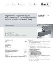
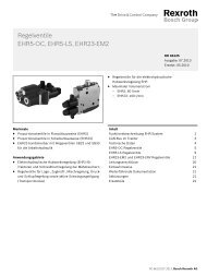
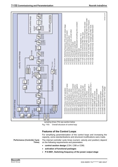
Fig. 7-63: Overall structure of control loop<br />
Features of the Control Loops<br />
P-0-0001, Switching frequency of the power output stage<br />
P-0-0004, Velocity loop smoothing time constant<br />
P-0-0040, Velocity feedforward evaluation<br />
P-0-0043, Torque-generating current, actual value<br />
P-0-0051, Torque/force constant<br />
P-0-0109, Torque/force peak limit<br />
P-0-0180, Acceleration feedforward smoothing time constant<br />
P-0-0640, Cooling type<br />
P-0-1119, Velocity mix factor feedback 1 & 2<br />
P-0-1120, Velocity control loop filter: filter type<br />
P-0-1121, Velocity control loop filter: limit frequency low pass<br />
P-0-1122, Velocity control loop filter: band-stop filter of band width<br />
P-0-1123, Vel. cont. loop filter: band-stop filter of center frequen<br />
P-0-1125, Velocity control loop: average value filter clock<br />
P-0-1126, Velocity control loop: acceleration feedforward<br />
S-0-0032, Primary mode of operation<br />
S-0-0037, Additive velocity command value<br />
S-0-0051, Position feedback 1 value<br />
S-0-0053, Position feedback 2 value<br />
S-0-0081, Additive Torque/Force command<br />
S-0-0082, Torque/force limit value positive<br />
S-0-0083, Torque/force limit value negative<br />
S-0-0091, Bipolar velocity limit value<br />
S-0-0092, Bipolar torque/force limit value<br />
S-0-0100, Velocity loop proportional gain<br />
S-0-0101, Velocity loop integral action time<br />
S-0-0104, Position loop Kv-factor<br />
S-0-0106, Current loop proportional gain 1<br />
S-0-0107, Current loop integral action time 1<br />
S-0-0109, Motor peak current<br />
S-0-0110, Amplifier peak current<br />
S-0-0111, Motor current at standstill<br />
S-0-0124, Standstill window<br />
S-0-0155, Friction compensation<br />
S-0-0348, Acceleration feedforward gain<br />
S-0-0380, Intermediate DC bus voltage<br />
For simplifying parameterization of the control loops and increasing the<br />
capacity, some standardizations and structural modifications were made.<br />
The internal controller cycle times (current, velocity and position) depend<br />
on the following requirements and parameters:<br />
• control section design (CSH, CSB or CDB)<br />
• activation of functional packages<br />
• P-0-0001, Switching frequency of the power output stage<br />
DF0001v2.fh7<br />
DOK-INDRV*-FU*********-IB01-EN-P